OEM DISPLAY INTERCONNECTS
Drawing-based DVI cable assemblies for industrial displays, embedded equipment and legacy video systems. Define the interface, routing and acceptance requirements around your equipment.
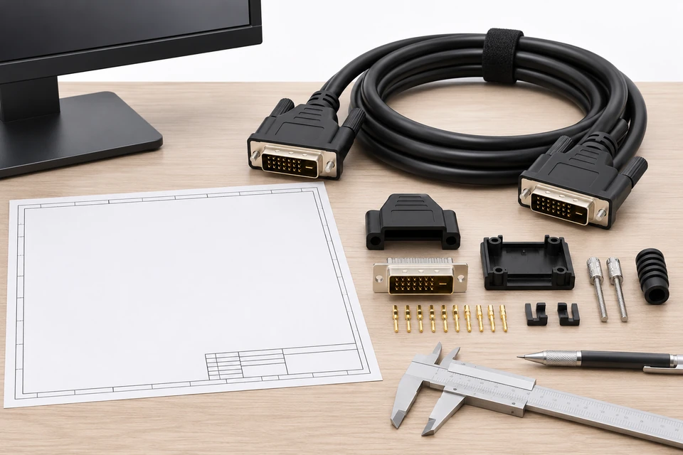
Xinshao supports custom cable assembly development from drawings, samples and BOMs. For DVI projects, start with the source and display interfaces, then define the cable construction and mechanical fit.
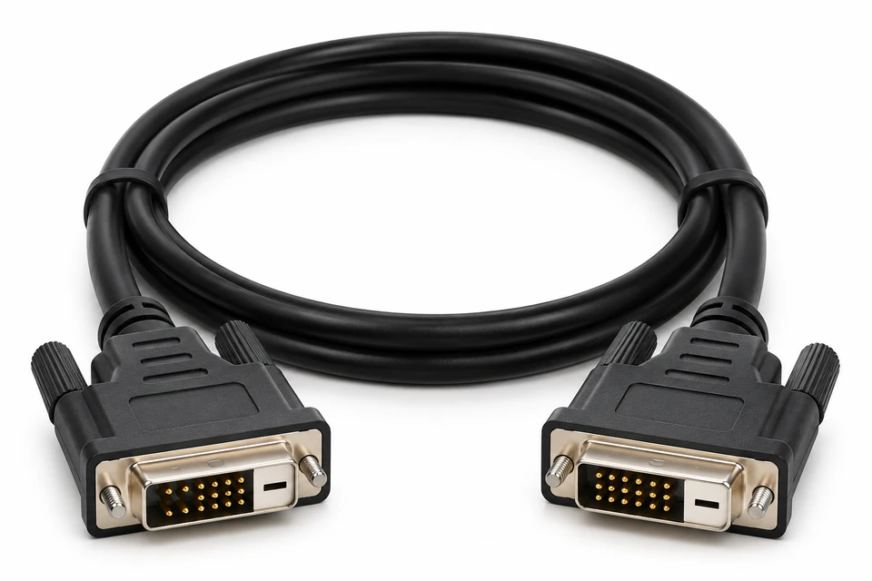
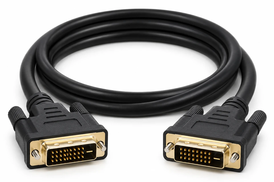
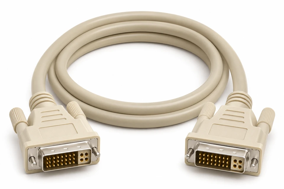
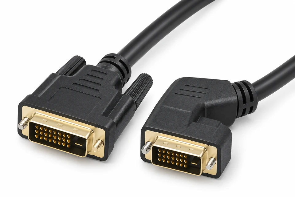
A connector shape alone does not establish compatibility. DVI-D carries digital signals; DVI-I can provide digital and analog paths when the connected equipment supports them. Single-link and dual-link requirements must be specified explicitly. The configurations below are RFQ directions, with final feasibility subject to drawing and component review.
Specify digital-only connections, mating connector gender and the required display timing.
Define dual-link wiring with the source, display and required timing before sample approval.
Review digital and analog circuit requirements against the exact equipment interfaces.
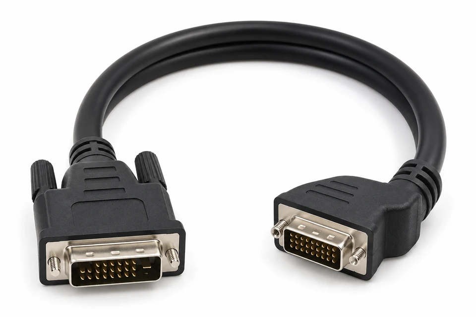
Confirm exit direction, backshell clearance and thumbscrew access from an enclosure drawing.
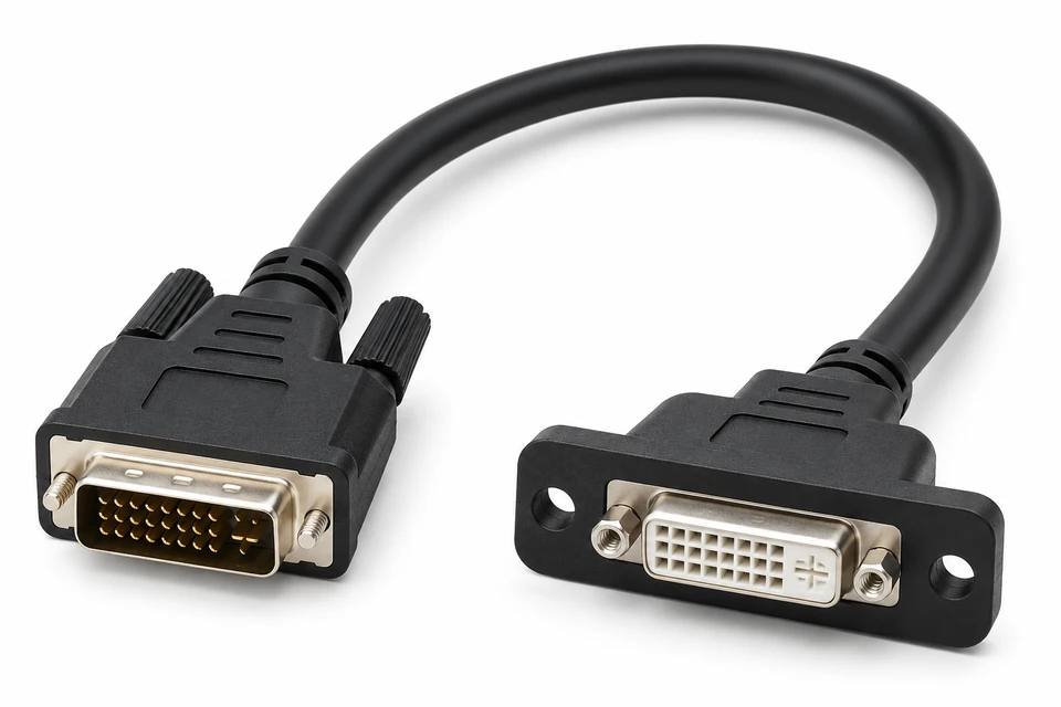
Specify male-to-female connections, flange position and mounting dimensions for enclosure integration.
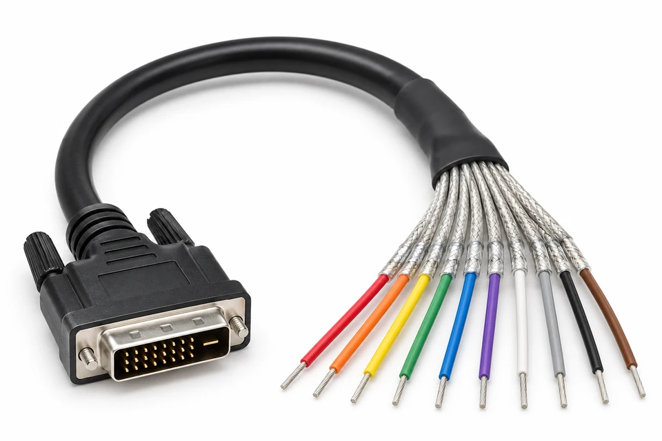
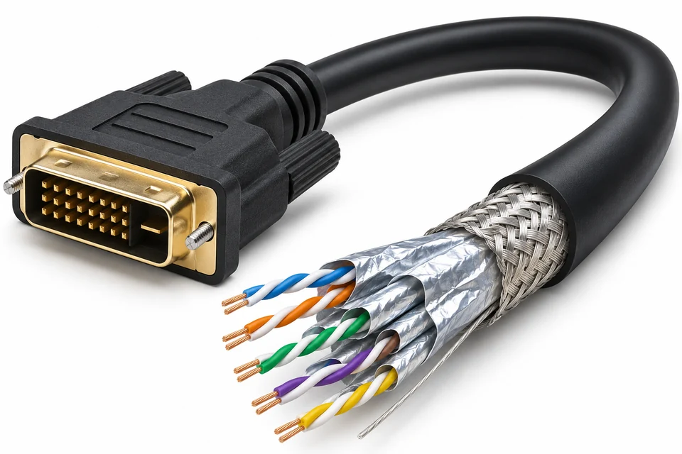
Develop drawing-based terminations with an approved pin map, shield treatment and destination connector.
6 Configuration Options
01
Align signal type, link wiring, gender and connector mating before procurement.
02
Review cable exit direction, connector envelope and screw access in your enclosure.
03
Agree the BOM, pin map, approved alternatives and labeling for repeat orders.
04
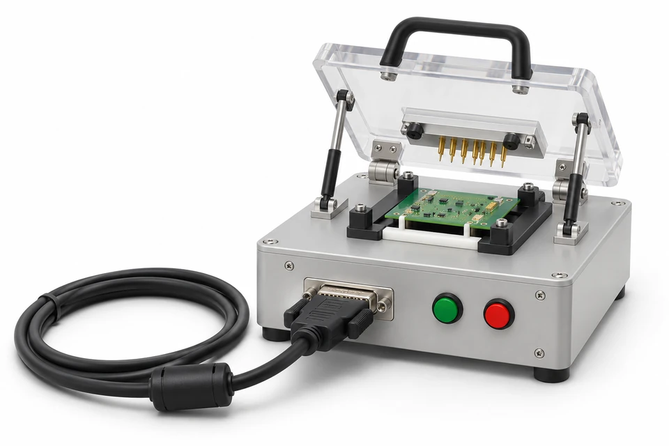
Plan continuity checks and application validation against the approved specification.
Send equipment interface references, target resolution and refresh rate, cable length and routing conditions. Cable losses and the source/display combination affect the usable signal margin; a universal maximum length or resolution is not assumed.
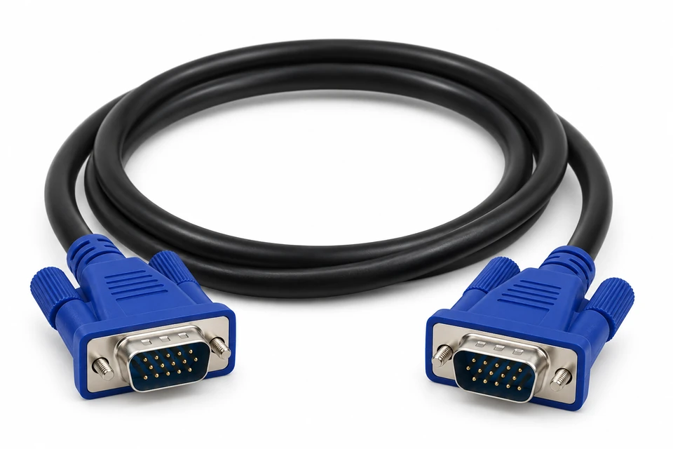
For supplier review, request the proposed BOM, drawing revision, inspection plan and sample validation criteria. A passive DVI-D cable cannot convert a digital signal into VGA analog video. Conversion requirements need a separate architecture review.
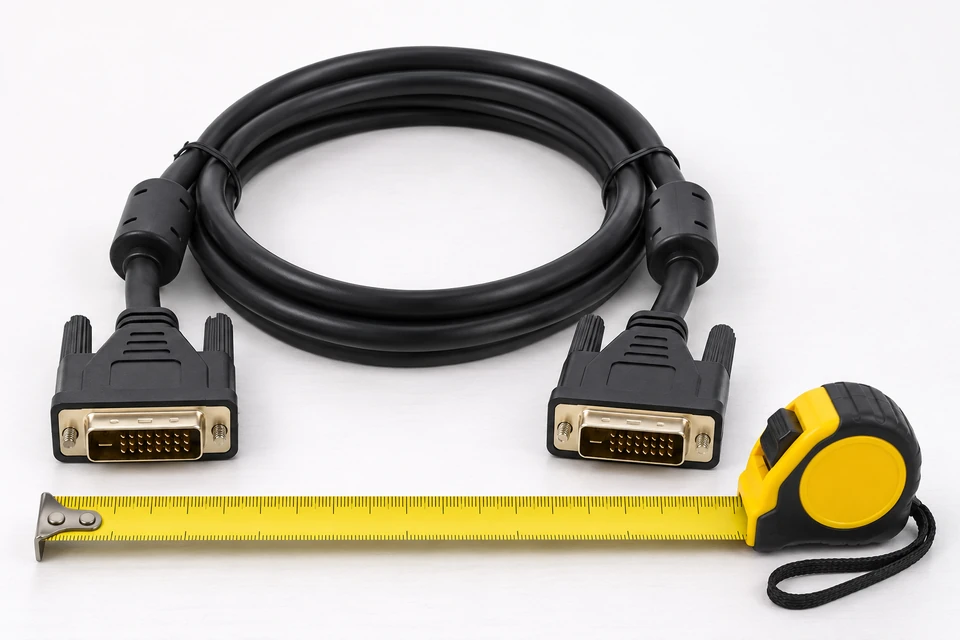
Define overall length and measurement points, tolerance, cable diameter, connector gender, exit direction, backshell size and retention hardware. Include installation photos or an enclosure drawing when clearance is limited.
Specify single-link or dual-link wiring and any required analog paths, DDC/EDID connections, shield continuity and chassis grounding. A populated connector does not by itself confirm the circuits used by the equipment.
For moving installations, supply bend radius, travel, duty cycle and service environment. Jacket choice and flex validation require a project-specific assessment.
Review conductor construction, pair geometry, foil/braid coverage, drain arrangement, jacket and connector shell termination as a complete assembly.
Agree workmanship and electrical acceptance before manufacture. Basic wiring checks do not establish video performance at the required timing.
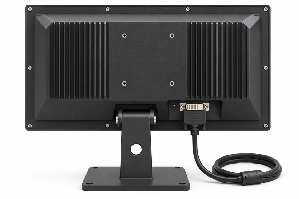
Review fixed display links for control cabinets, embedded systems and existing DVI platforms. Define service access, retention and enclosure constraints.
Coordinate drawings, material availability, annual demand and revision control. Evaluate replacement parts against an approved sample rather than connector appearance alone.
Resolve compatibility and validation requirements before placing a production order.