顶级制造商

OEM TELECOM INTERCONNECT SOLUTIONS

Telecom Cable Assembly Manufacturer

Custom RF, data, optical and power interconnects for telecom equipment OEMs. Send your drawing, BOM and link requirements for a manufacturing review.

  • Drawing, sample and BOM-based development
  • Connector, cable and routing customization
  • Prototype and production project support

Xinshao — Custom Telecom Cable Assemblies

Xinshao supports drawing-based cable assembly development for communication equipment, network cabinets and embedded telecom hardware. Coordinate RF, data, optical and power interfaces around your equipment layout.

Share exact mating part numbers, lengths, routing constraints and operating conditions. We review component sourcing, termination access and inspection requirements before samples; approved sample and drawing revisions provide the basis for production.

Explore Telecom Cable Assembly Options

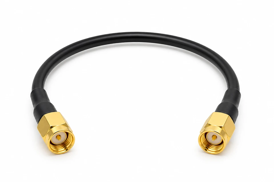
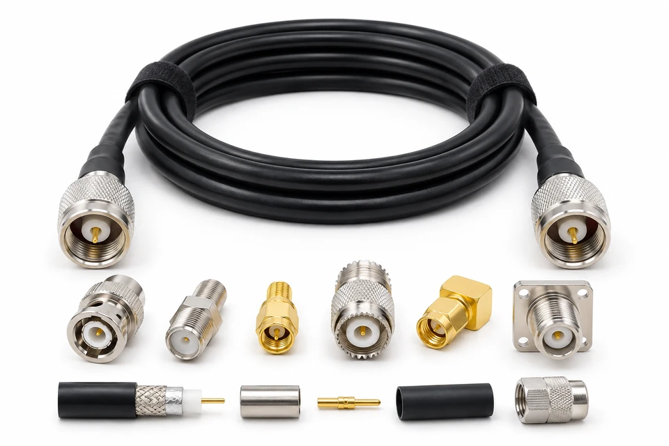
telecom-rf-jumper

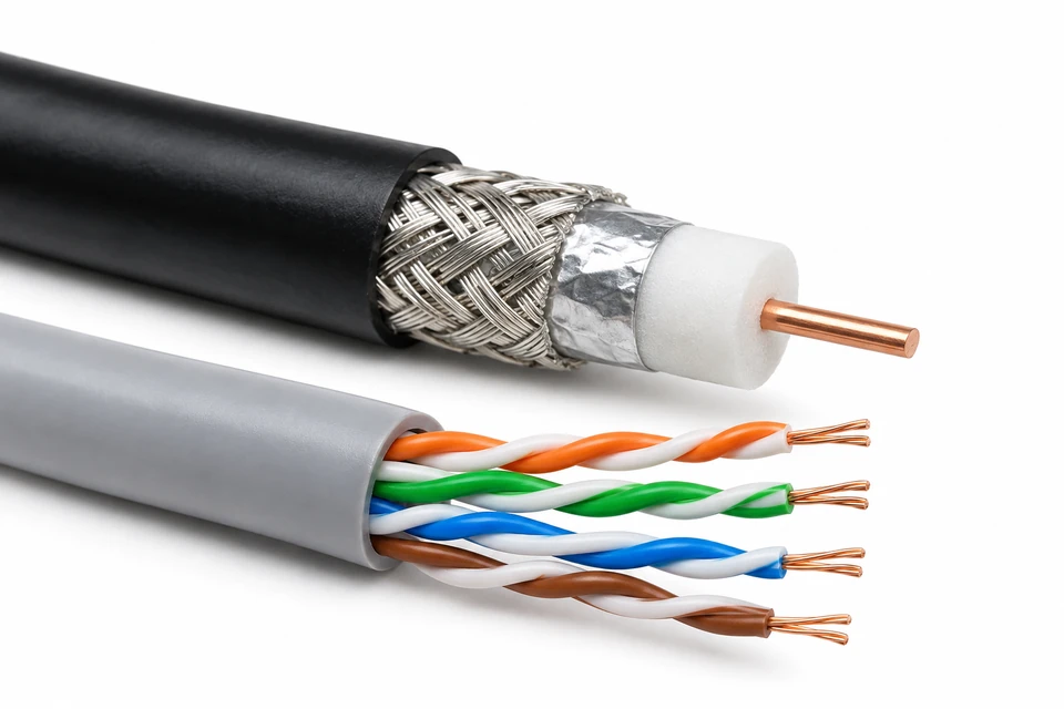
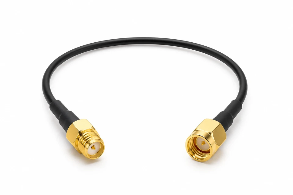
RF Jumper Cable Assemblies

Specify connector interfaces, cable construction, operating band and the assembled loss limits for radio equipment interconnects.

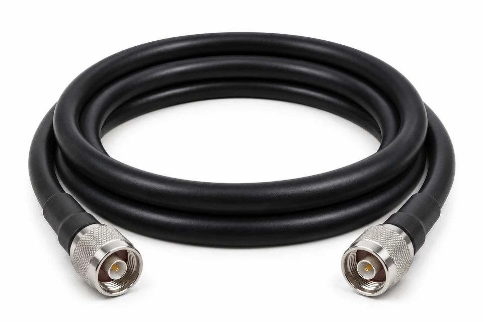
telecom-coaxial-feeder

Coaxial Feeder Assemblies

Define feeder routing, connector orientation, bend clearance and environmental protection for your equipment installation.

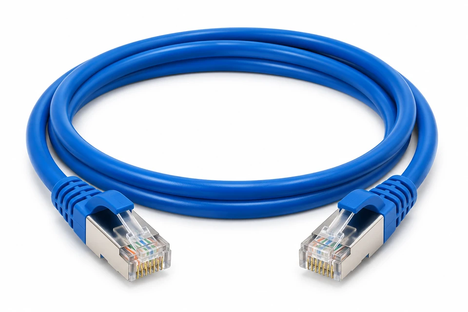
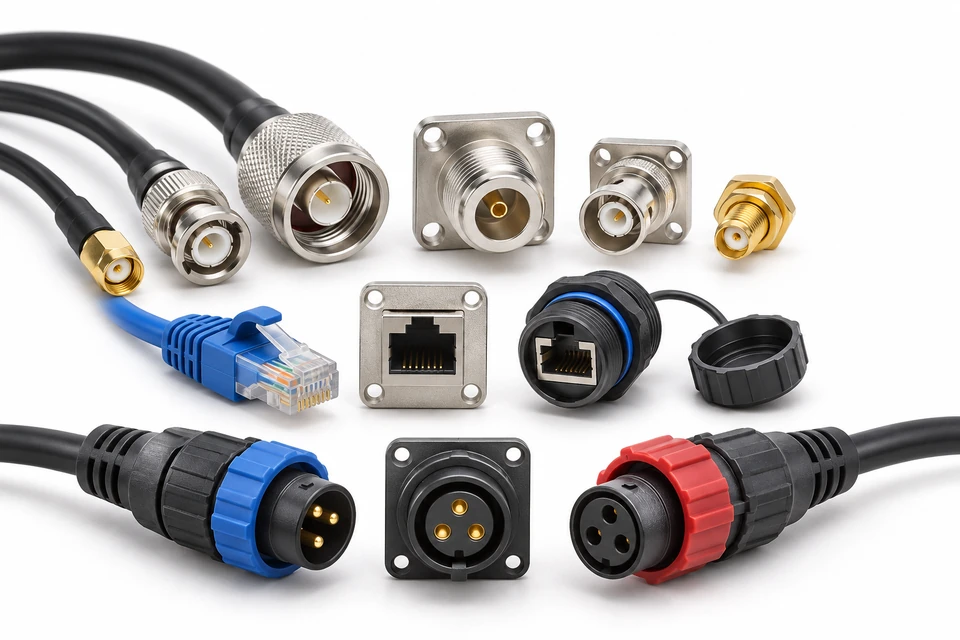
telecom-ethernet-assembly

Ethernet Cable Assemblies

Configure shielded patch and equipment links around the required channel specification, length and mating interface.

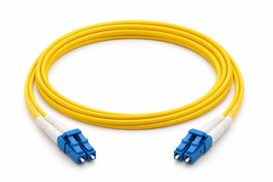
telecom-fiber-patch

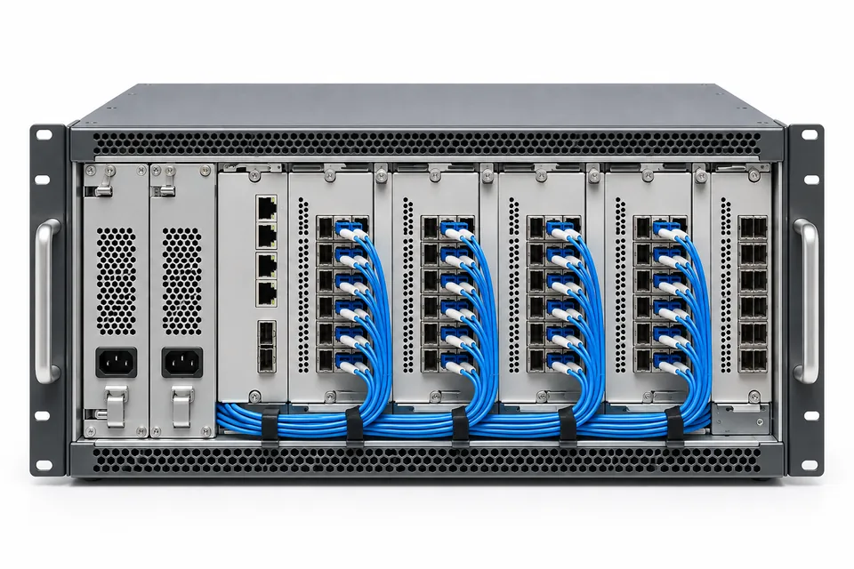
Fiber Optic Patch Assemblies

Define fiber type, connector and polish combination, polarity and optical acceptance criteria for the complete link.

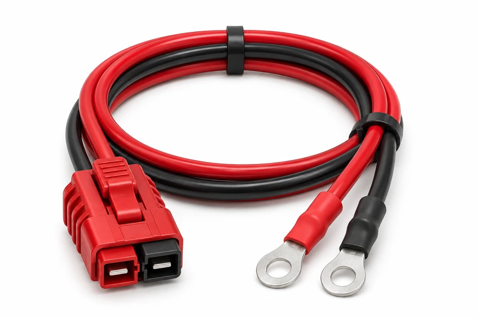
telecom-power-harness

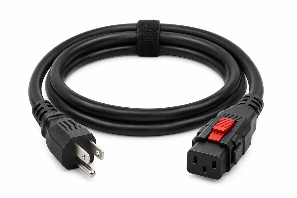
Telecom Power Harnesses

Configure DC equipment feeds with approved conductor size, polarity, locking interfaces and branch dimensions.

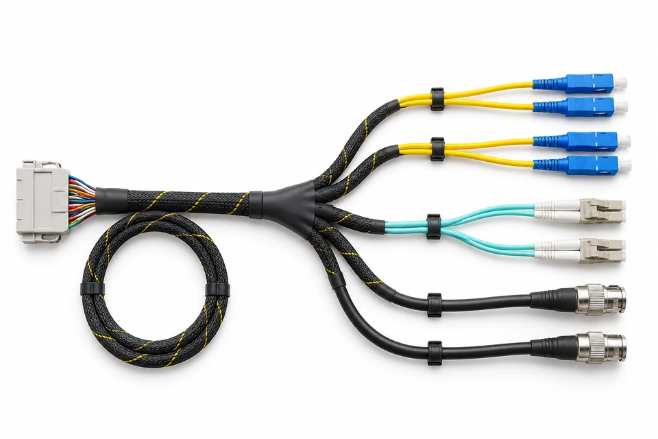
telecom-signal-harness

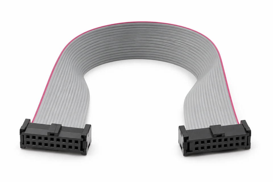
Internal Signal Harnesses

Build drawing-based control and signal interconnects with defined pinouts, retention, shielding and identification.

6 Products Found.

Built Around Your Assembly Requirements

01

Design Flexibility

Specify connectors, wire lengths, branching, protection and labeling for your installation.

02

Engineering Review

Discuss your drawings and assembly requirements before starting a new build.

03

Scalable Support

Plan prototype and production requirements around the needs of your project.

04

Project Coordination

Align drawings, revisions and inspection requirements before manufacture.

Evaluate Your Telecom Cable Assembly Supplier

Assess the complete assembly against your interface and link requirements. Matching connector names alone does not establish RF, Ethernet or optical performance. Agree component sources, permitted substitutions and test evidence before ordering.

RFQs should define frequency band and impedance, channel or optical link requirements, cable length and tolerance, shielding termination, bend clearance and service environment. Any ingress rating or signal limit applies to the specified construction and test conditions.

telecom-supplier-review

Configure the Interfaces, Routing and Acceptance Plan

telecom-routing-design
telecom-connector-options

Define connector part numbers and genders, cable construction, pin mapping, branch lengths, label format and chassis ground connections. Identify the installation envelope and minimum routing clearances in the drawing.

Review the BOM and available components, build samples, approve dimensions and test results, then release the controlled revision for production. Alternative components require customer approval; optical polish and mating combinations must be explicitly specified.

For quotation, include sample quantity, production quantity, estimated annual use, required reports and delivery destination. Lead time and tooling costs depend on component availability and validation scope.

telecom-cable-materials

Cable, Shielding & Connector Selection

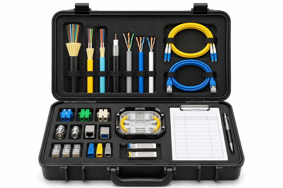
Review electrical, optical and mechanical requirements separately for each assembly family. Select jacket and protection for actual installation conditions.

  • RF impedance and cable construction; fiber type and polish
  • Exact mating interfaces, pin mapping and connector orientation
  • Jacket, shield bonding, strain relief and traceability requirements
telecom-termination-process

Termination & Verification Planning

Agree inspection and acceptance criteria before the sample build. Routine dimensional and connection checks are distinct from application validation.

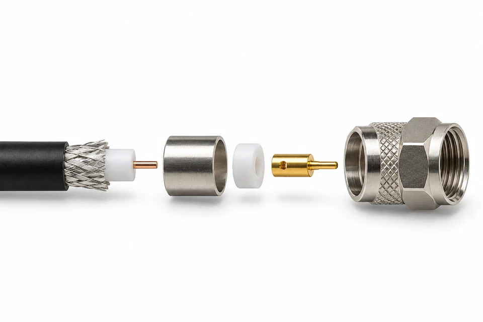
  • Crimping, stripping and connector assembly to approved instructions
  • Pinout, polarity, dimensions, retention and visual inspection
  • RF loss/return loss, optical loss or channel tests when specified

Who We Support

telecom-equipment-oem

Telecom Equipment OEMs

Coordinate radio, networking and cabinet interconnects against controlled BOMs. Confirm connector access, cable routing and service replacement requirements before release.

telecom-procurement

Engineering & Procurement Teams

Compare component availability, approved alternatives, test reporting and revision control alongside unit price. Include sample approval effort and qualification costs in sourcing decisions.

Telecom Cable Assemblies:RFQ & Engineering Guide

Prepare the right project information for a more useful engineering review and quotation.

Send the drawing, BOM, exact connector part numbers and mating interfaces, cable specification, lengths and tolerances, pinout or polarity, sample and annual quantities, test requirements and delivery destination. Send available information first if the design is incomplete.
No. Confirm the specified cable, termination, length and complete assembly acceptance criteria. RF, copper data and optical links need different validation plans; connector appearance alone is insufficient.
For RF links, define the operating band and agreed insertion and return loss limits, including the test reference planes. For fiber links, specify fiber type, connector polish, polarity and optical loss criteria. Reports and test scope should be agreed at quotation.
Any alternative should be identified and approved against mating, electrical and mechanical requirements. A similar connector housing does not establish equivalent performance or compliance.
Connector availability, cable sourcing, tooling, design changes and application testing affect timing. Confirm delivery dates after BOM review and sample approval rather than relying on a generic lead time.
Provide the installed environment, mating state, sealing interfaces, UV exposure and required ingress test conditions. Protection must be assessed for the complete design; it is not implied by a connector family name.

Send Your Inquiry Today

Send Your Inquiry Today