DRAWING-BASED OEM INTERCONNECTS
Xinshao supports custom coaxial cable assembly projects for equipment OEMs. Bring your connector part numbers, cable specification and RF acceptance requirements to a focused manufacturing review.
Source an assembly around the signal path and mechanical installation. Xinshao works with OEM engineering and procurement teams on drawing-based cable projects, from component selection through sample review and production planning.
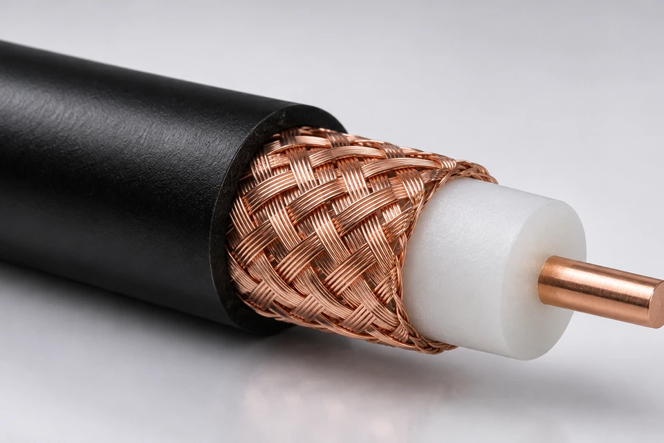
Start with the exact mating interfaces, cable construction, length datum and operating conditions. RF performance belongs to the complete cable-and-connector combination; acceptance limits and test coverage should be agreed for each design.
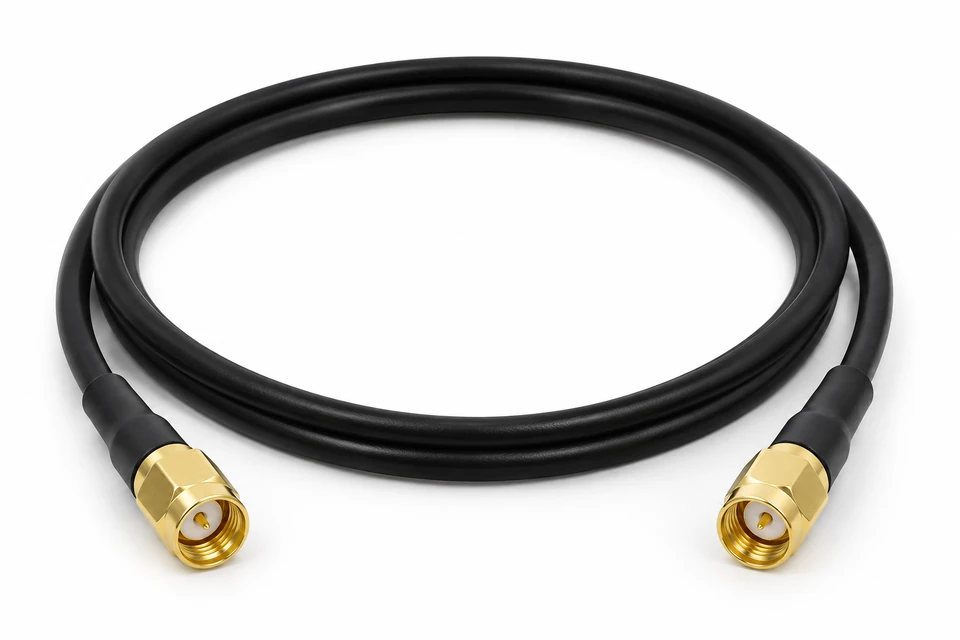
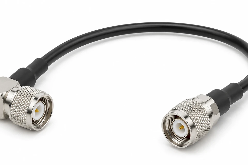
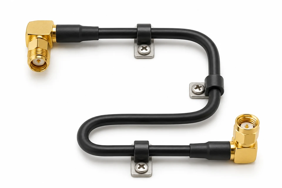
Specify straight or right-angle interfaces, exact connector gender and mating requirements. Confirm the cable and connector combination against your operating band.
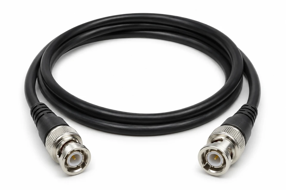
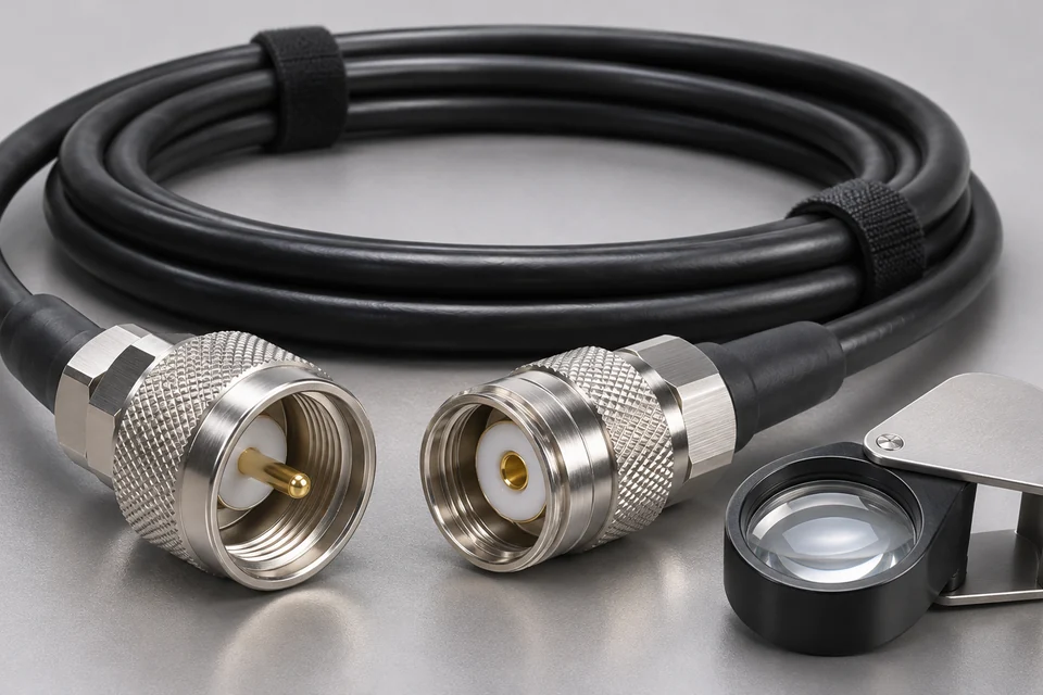
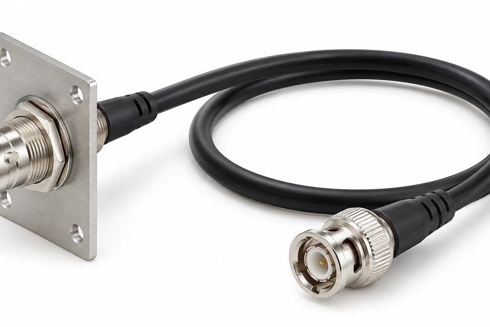
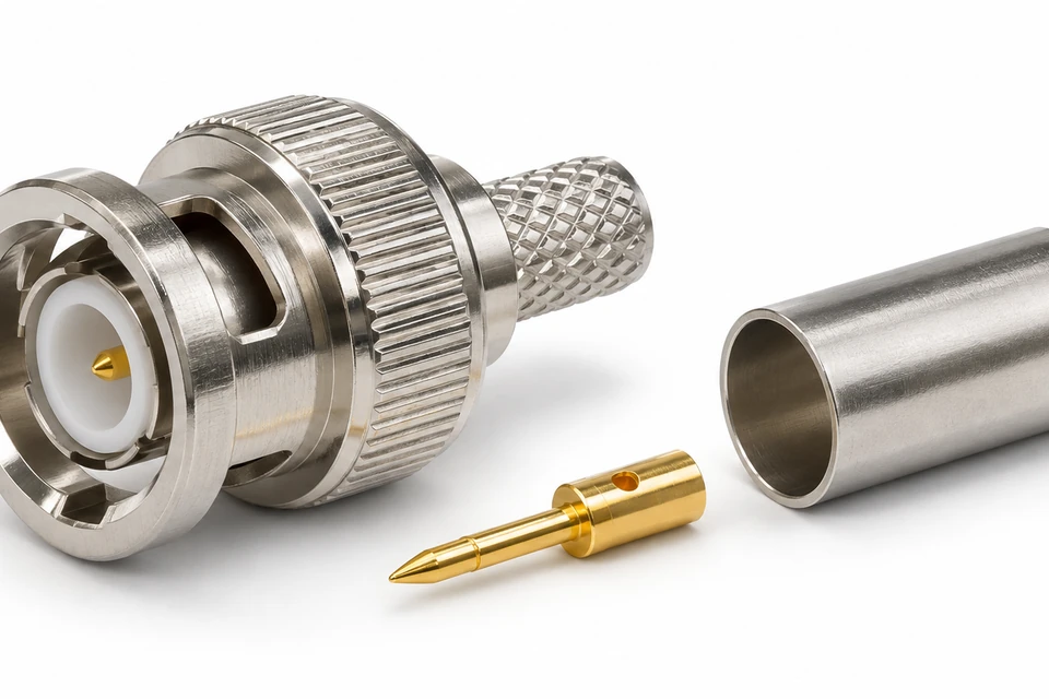
Define the required impedance, bayonet interface and cable construction for instrumentation or video equipment. Similar-looking interfaces require part-number confirmation.
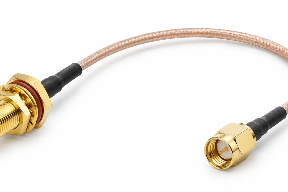
Share the installation envelope, mating connector and environmental conditions for equipment interconnects. Sealing requirements apply to the complete installed assembly.
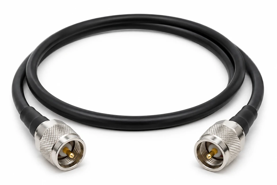
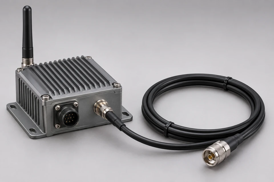
Review threaded interfaces, connector orientation and cable routing for your equipment. Include vibration and retention requirements in the drawing.
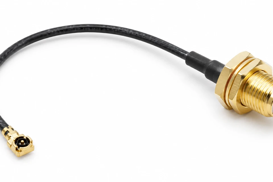
Provide the exact board connector series, mating height, cable diameter and routing space. Miniature snap-on families are not automatically interchangeable.
Define panel thickness, mounting hardware, connector clocking and internal cable length. Review access for assembly and mating before freezing the design.
6 Configuration Options
01
Confirm mating part numbers, gender, polarity and connector orientation.
02
Align impedance, attenuation needs and routing with the cable specification.
03
Record approved drawings, BOM revisions and substitution approvals.
04
Define electrical checks and any project-specific RF verification before production.
A coaxial supplier review should cover connector sourcing, cable availability, termination methods and drawing control. Request evidence relevant to the proposed assembly rather than relying on a generic capability list.
Agree sample approval criteria, traceability needs and inspection records. Continuity checks alone do not establish insertion loss, return loss or performance across an operating band.
Specify length between clearly defined reference planes, dimensional tolerances, connector angle and clocking. Include panel thickness, tool clearance and the permitted cable route.
Confirm the minimum bend radius from the selected cable specification and distinguish fixed installation from repeated movement. Avoid using a connector body as strain relief.
Share your drawing, sample or current component list. Missing details can be identified during review before a sample build is agreed.
Choose the complete signal path around the equipment requirements.
Manufacturing requirements follow the selected component instructions and approved assembly drawing.
Coordinate internal RF connections, panel interfaces and service access with the wider equipment design. Include operating environment and installation constraints in the RFQ.
Compare approved components, sample evidence, purchasing quantities and revision control. Evaluate alternatives explicitly before changing a qualified BOM.
Define the interface and the acceptance criteria before comparing quotations.