DRAWING-BASED CABLE ASSEMBLIES FOR OEM EQUIPMENT
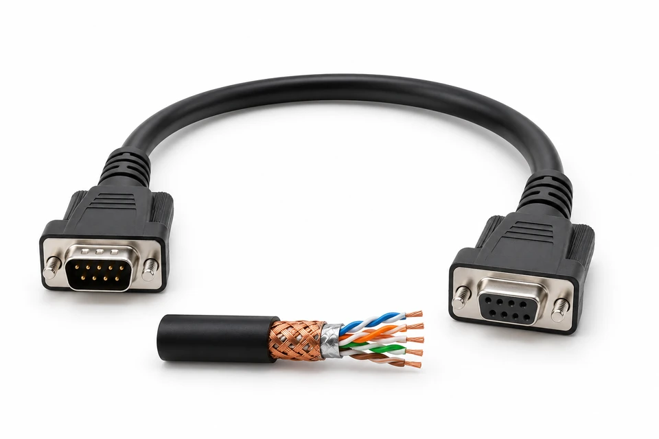
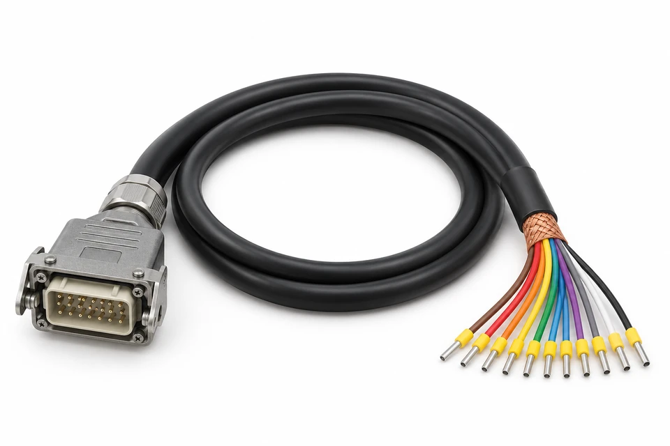
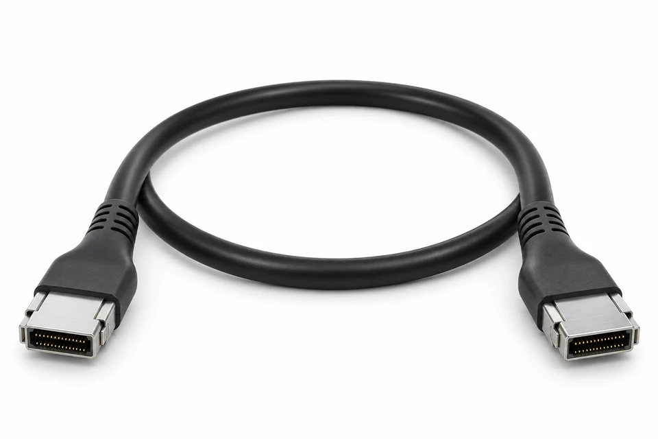
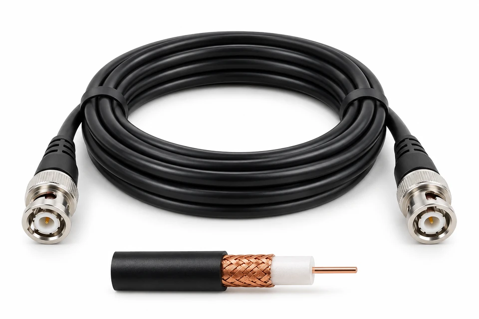
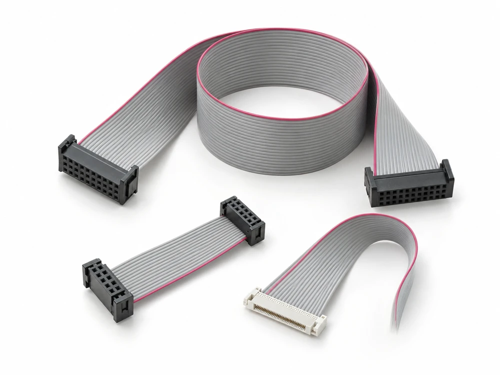
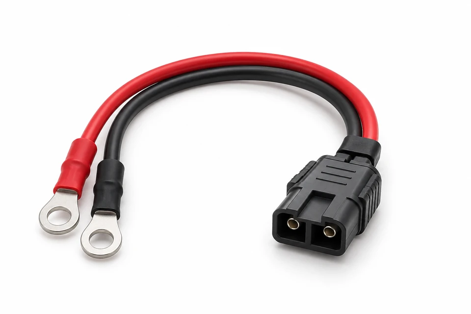
Xinshao manufactures custom shielded cable assemblies for industrial controls, automation, instrumentation and electronic equipment.
Bring your drawings, BOM, connector requirements or an existing sample. Xinshao reviews the cable construction, pinout, shield termination and installation requirements against your application.
From an individual signal connection to a branched assembly, define both the electrical connections and how the shield connects at each interface. Shijiazhuang Xinshao Electronic Technology Co., Ltd. supports OEM/ODM cable interconnection projects from design and prototyping through production.
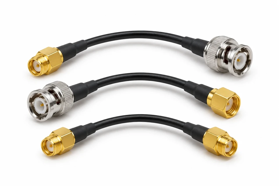
Define signal circuits, overall shielding and connector-shell connections for your equipment.
Specify sensor interfaces, pair assignments and drain-wire connections in the approved drawing.
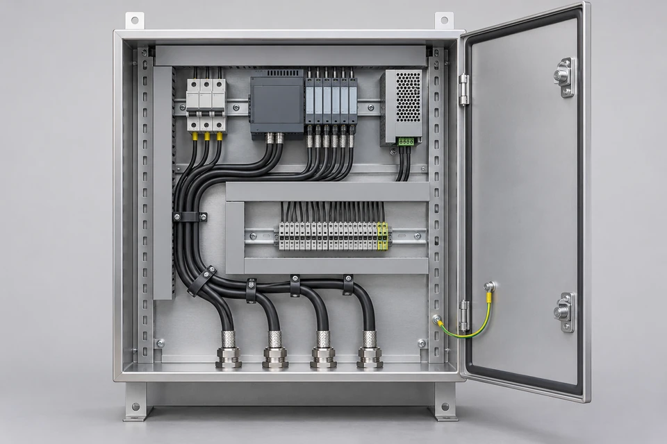
Coordinate control circuits, cable routing and shield connections at cabinet interfaces.
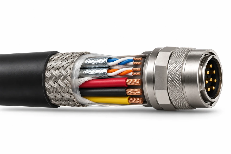
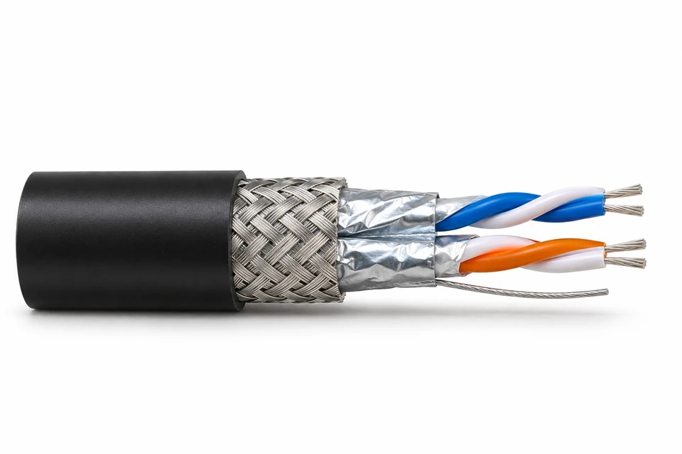
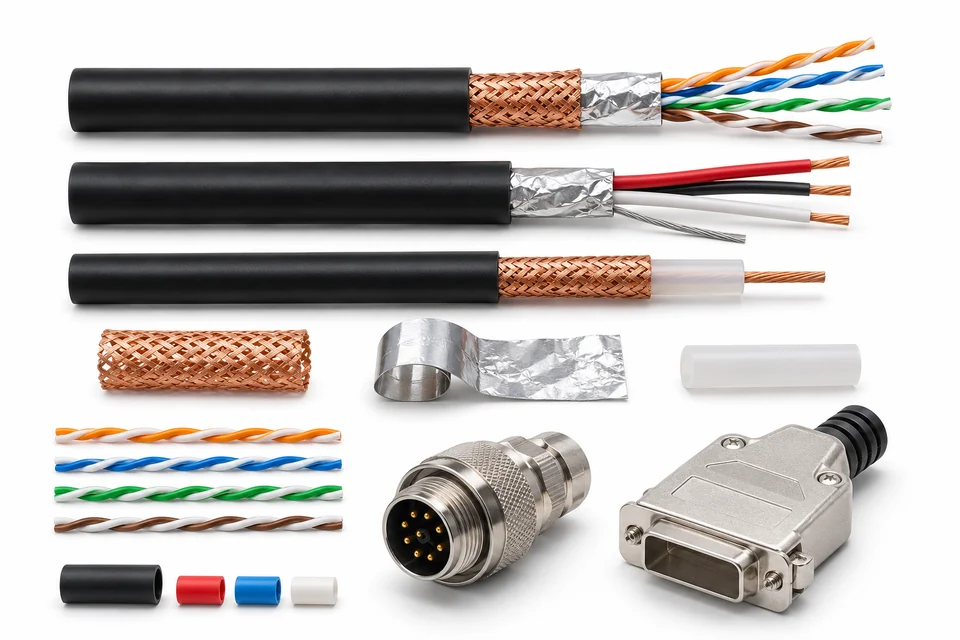
Review separate circuit groups, pair shields and the overall shield arrangement.
Document branch positions, breakout lengths and shield transitions across each branch.
Review strain relief, tooling and concealed termination inspection before approving the construction.
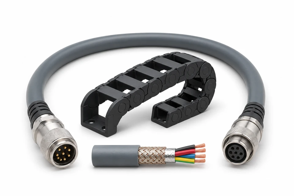
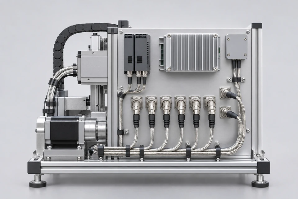
Provide bend radius, travel, torsion and expected cycles for cable and termination review.
Use drawings or a sample to establish pinout, materials and acceptance criteria for repeat builds.
8 Assembly Options · 6 per page
01
Build the discussion around your interfaces, routing space and approved requirements.
02
Identify original components and any proposed alternatives for customer approval.
03
Evaluate fit, routing and electrical connections before authorizing repeat production.
04
Agree FAI, test records and traceability scope during quotation.
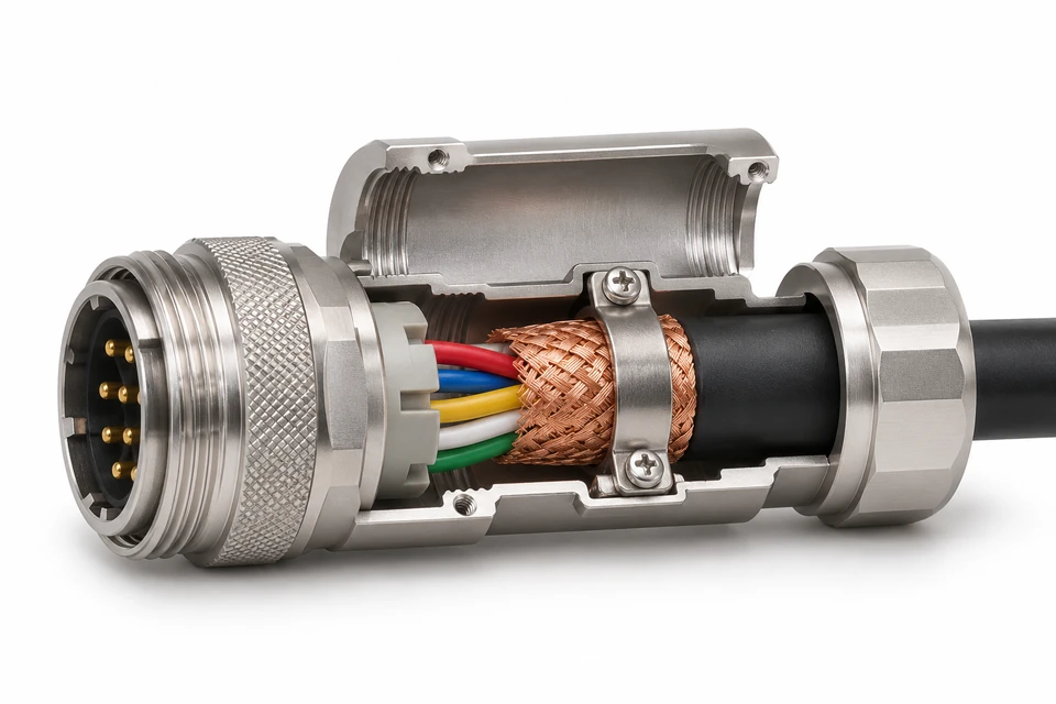
Show where each shield connects: a connector shell, backshell, chassis connection, designated contact or another defined termination point. Include intermediate connectors and branch transitions.
Where circumferential termination is required, the selected connector and backshell must support that construction. A drain-wire connection and a circumferential termination are different arrangements; identify the required method in the drawing.
Specify overall shielding, individually shielded pairs or groups, and the connection required at each end. Supply the grounding diagram rather than leaving the assembly supplier to infer the equipment grounding arrangement.
Include bend space, connector exit direction and cable supports. For repeated motion, provide travel, speed, bend radius, torsion and expected operating cycles for engineering review.
Shielding alone does not define impedance, insertion loss, timing or data-rate performance. Include the relevant interface and validation requirements when the assembly carries high-speed signals.
These are design inputs, not a published capability range. Final feasibility depends on the selected components and approved construction.
Complete part numbers, keying, shell and backshell requirements.
Wire gauge, conductor count, twisted pairs and operating electrical requirements.
Pin-to-pin map, unused contacts, shield construction and connection at each interface.
Length reference points, tolerances, branches, strain relief and overmolding.
Temperature, chemical exposure, routing space, fixed or moving duty.
Inspection criteria, electrical limits, sample approval and traceability scope.
Select cable, connectors and protection around the equipment requirements. Proposed alternatives need customer approval and may require additional validation.
Xinshao supports custom assembly, shielding and overmolding. Review the required tooling and inspection access for the selected construction.
A continuity result can confirm a defined electrical connection. It does not establish shielding effectiveness or the finished equipment’s EMC performance.
If shielding-effectiveness measurements, signal-integrity validation or equipment-level EMC tests are required, specify the method, frequency range, fixture or installation conditions and acceptance limits. Agree validation responsibility and scope separately.
01
Identify missing dimensions, unclear shield connections and component availability issues.
02
Agree what samples must demonstrate: fit, routing, connections and termination construction.
03
Establish the drawing revision, approved BOM, acceptance criteria and change-control requirements.
04
Confirm material availability, quantities, documentation and validation needs before agreeing the schedule.
Specialized cable, connector hardware, tooling and external testing can affect both cost and timing. Sample and production schedules are quoted after project review.
Coordinate assembly routing, installation interfaces and production requirements for machinery, controls and instrumentation.
Align the drawing, BOM, component approvals, FAI requirements and test records before production sourcing.
Send the project information you already have. Open requirements can be identified during review before sample approval.