XINSHAO · OEM / ODM CABLE ASSEMBLIES
HD15 display connections configured for your equipment. Define the length, connector orientation, mounting details and pin assignment for your next OEM build.
A cable that fits the connector may still leave too little room for a backshell, introduce an awkward service loop or omit a circuit your display needs. Specify the complete assembly around the installation.
Xinshao supports drawing-based cable assembly development for equipment manufacturers and engineering teams. For VGA projects, share both mating interfaces, the required pin map, routing space and display operating conditions so the design can be reviewed before sampling.
Explore the configuration families below as starting points for an RFQ. Each assembly is subject to engineering review and an approved project specification.
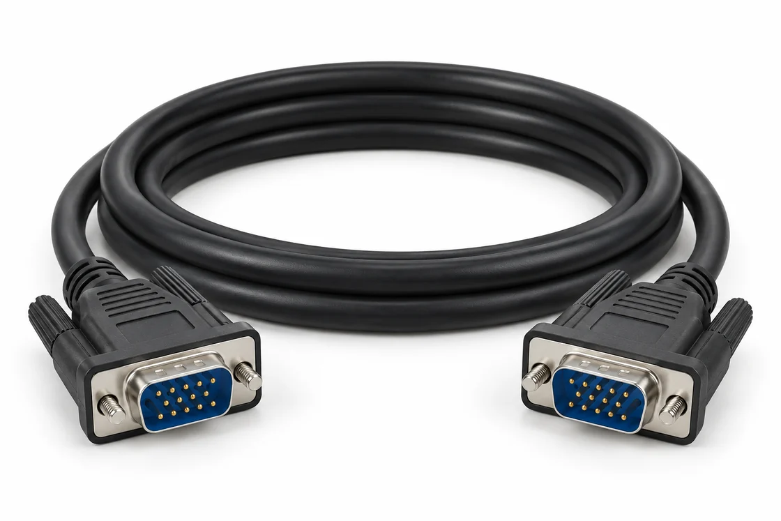
Drawing-defined monitor leads with specified length, pin population and connector hardware.
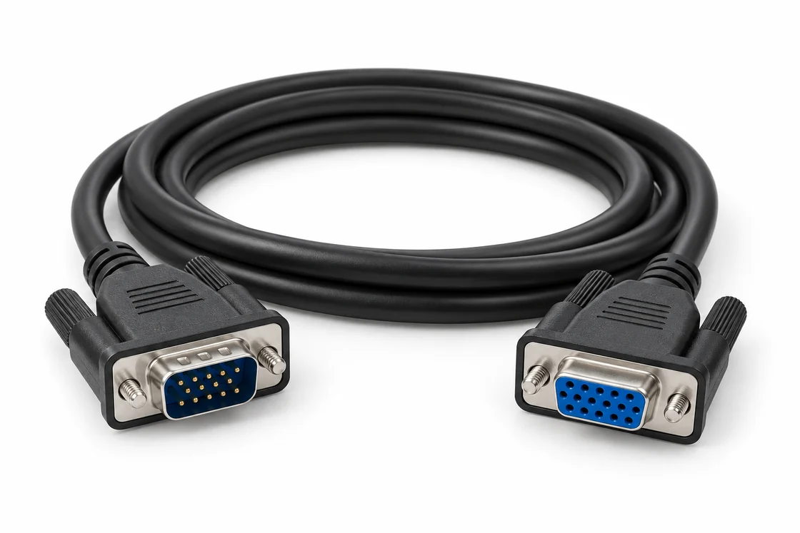
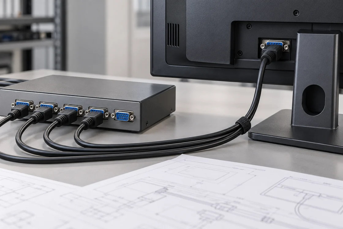
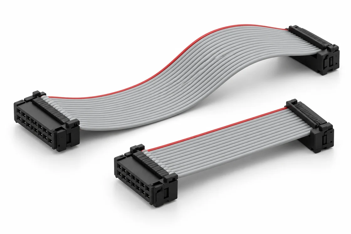
Male-to-female assemblies for service access and display connection extensions.
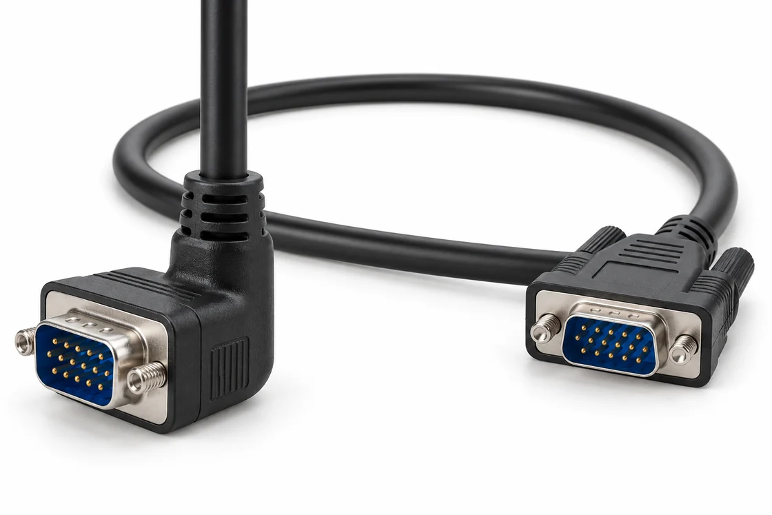
Connector exit direction and hood dimensions reviewed against enclosure clearance.
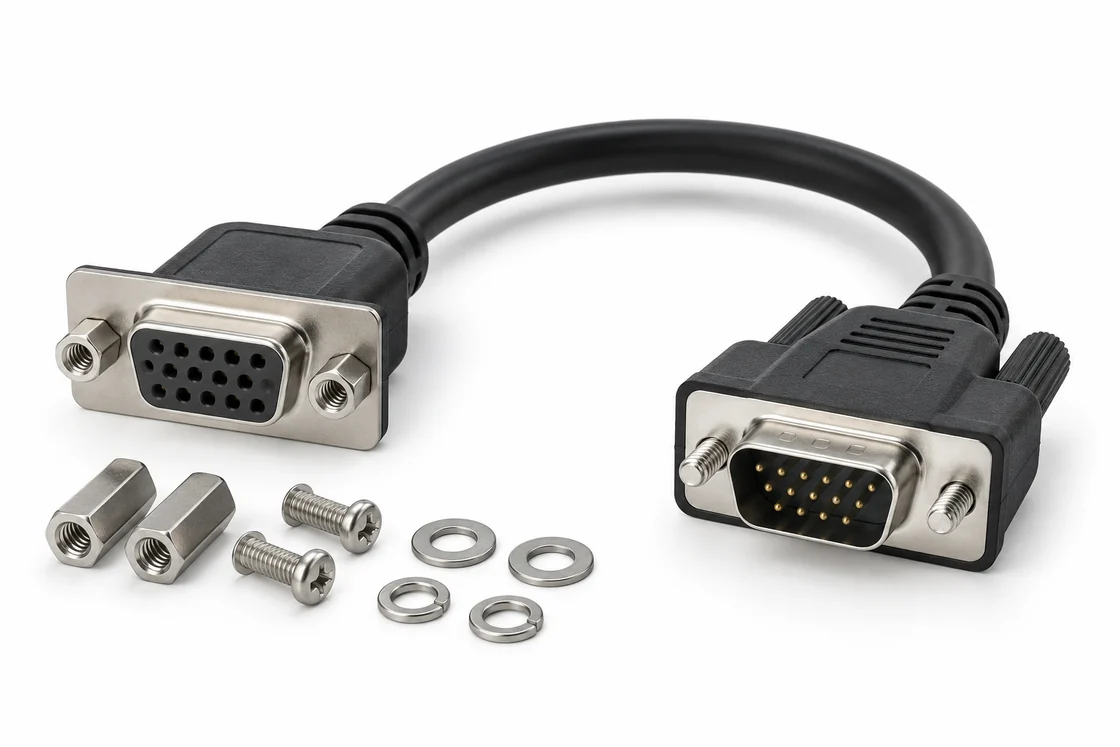
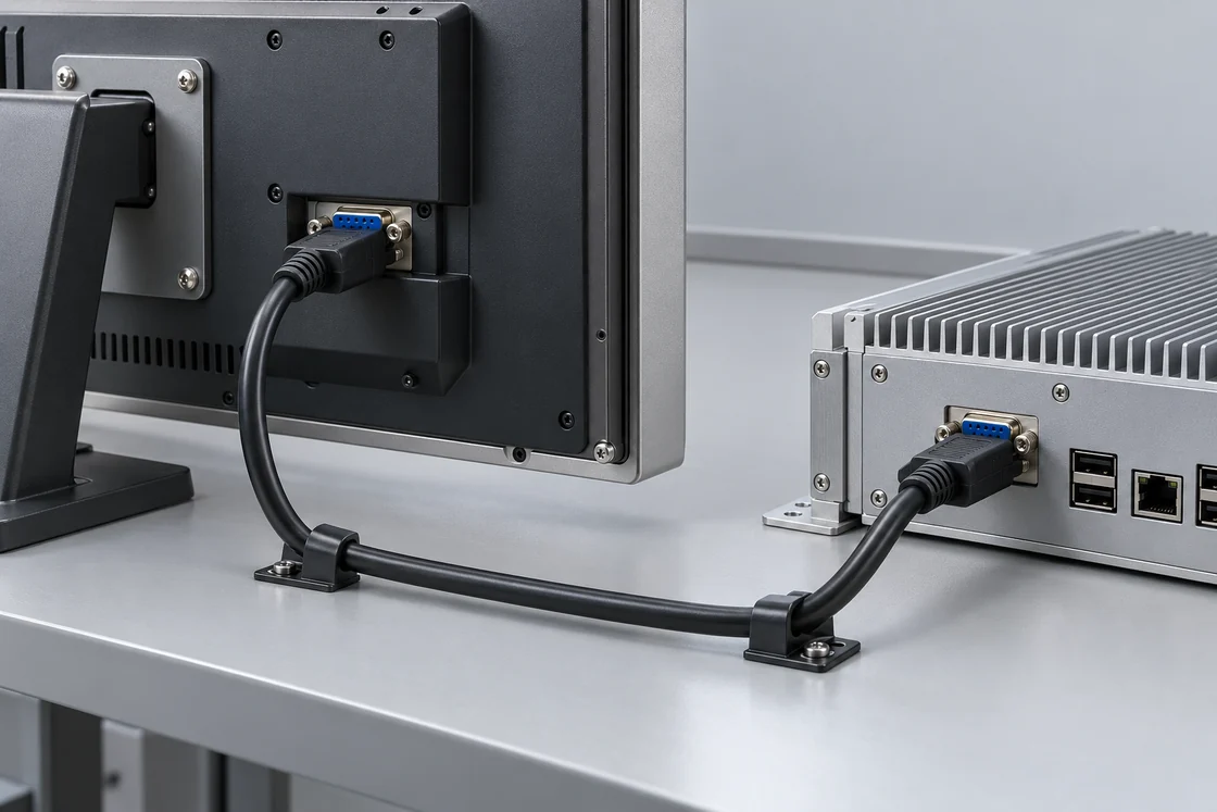
Panel interface, fasteners and internal cable routing specified for equipment integration.
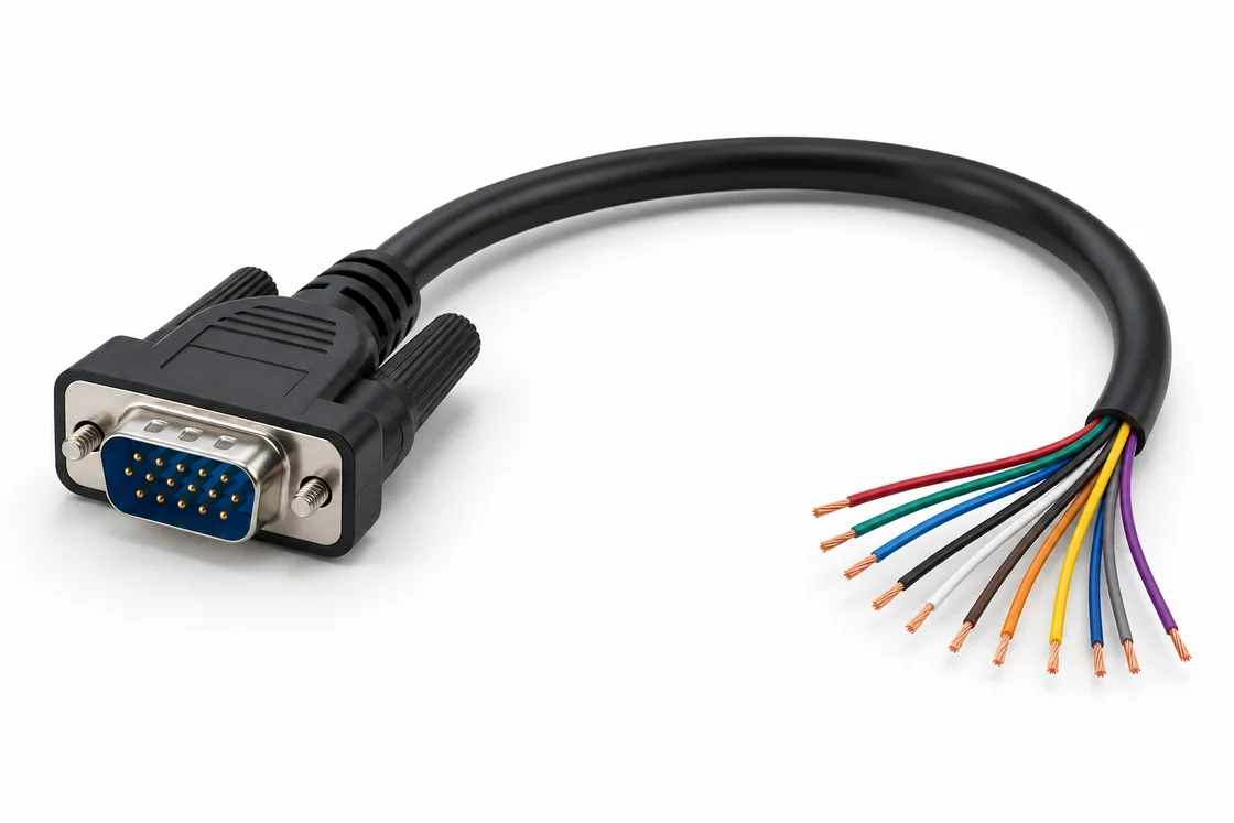
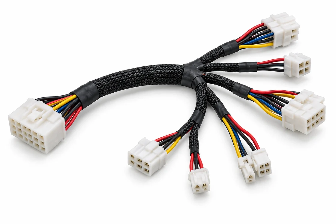
HD15 to prepared leads for equipment wiring, with each circuit defined in your pin map.
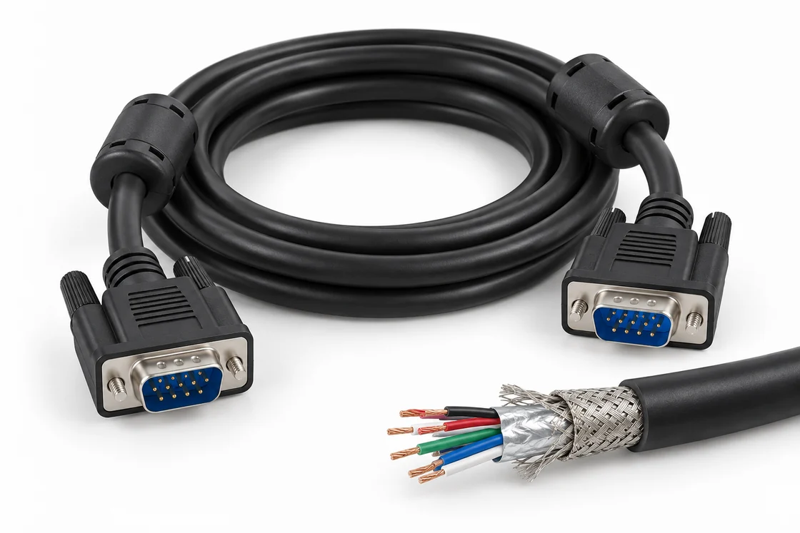
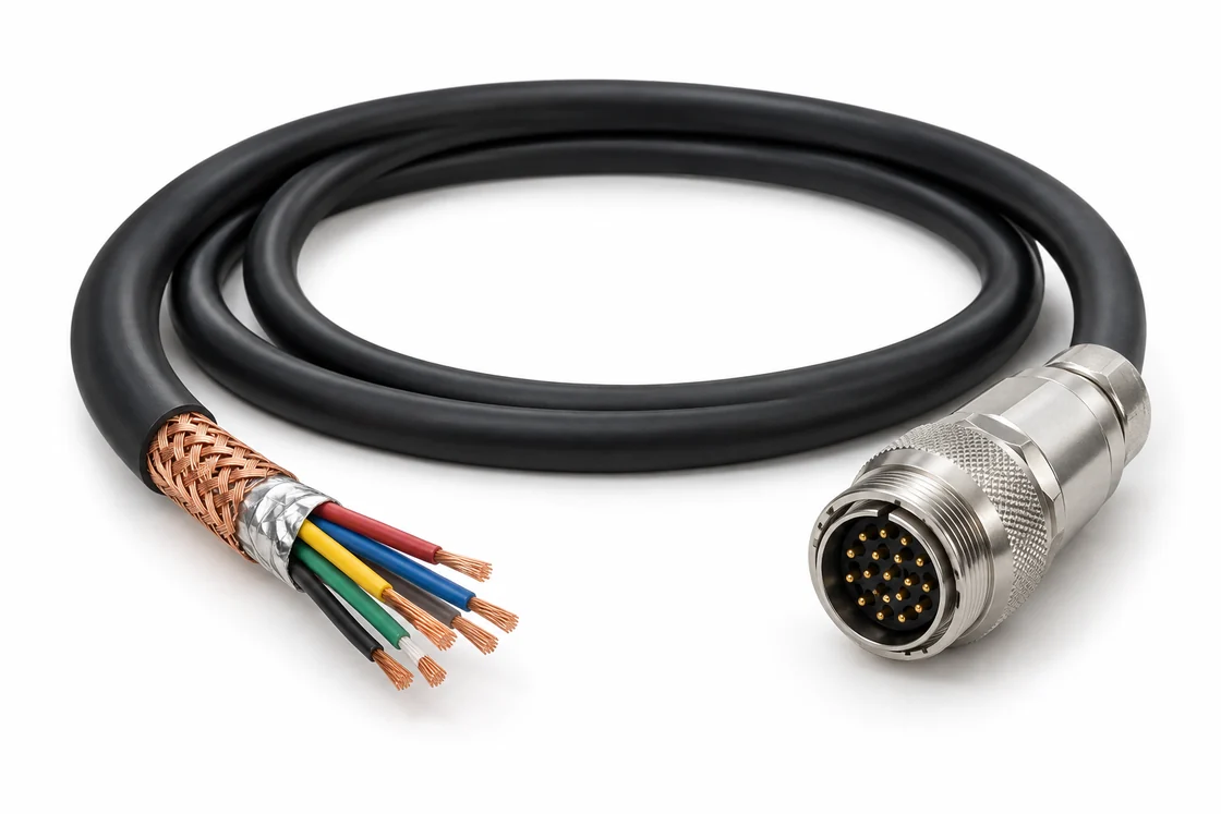
Cable construction, shield termination and optional ferrite placement reviewed for the system.
6 Configuration Families
Illustrations show configuration concepts, not stocked SKUs or verified production samples.
01
Review cable exit direction, hood envelope, mounting position and service access.
02
Use an approved pin map, including required display identification and control connections.
03
Coordinate BOM revisions, acceptable substitutions, labels and prototype acceptance.
04
Specify continuity, insulation and application checks appropriate to your assembly.
Xinshao works from customer drawings, samples and BOMs to support custom interconnect development, prototyping and production. Engineering review turns installation constraints into a defined assembly specification.
For a repeat build, agree connector part numbers, cable construction, finished-length tolerance, workmanship criteria and reporting requirements. Any requested compliance documentation must apply to the actual materials and assembly supplied.
Mechanical fit: identify connector gender at both ends, mating view, exit direction, maximum hood size, cable diameter, bend space and panel hardware.
Electrical definition: provide the complete pin-to-pin map and cable construction requirements. Review RGB paths, shielding, grounds and any required DDC/EDID connections against the connected equipment.
Production release: approve the sample and drawing revision, quantities, labeling, packaging and test criteria before the production order.
Choose construction around the signal path, installation and operating environment.
Translate the released drawing into agreed production and acceptance requirements.
Define panel connections and internal routing for industrial displays, embedded controllers and equipment service programs.
Source drawing-defined VGA monitor cables, extension leads and replacement assemblies for installed analog display systems. Confirm interfaces before purchasing.
Discuss related projects through the inquiry form.
Use these checks to prepare a comparable RFQ and reduce sample revisions.