OEM BATTERY INTERCONNECT SOLUTIONS
Drawing-based battery power, BMS sensing and temperature-sensor harnesses for OEM battery packs and equipment. Send your pinout, BOM and installation requirements for a manufacturing review.
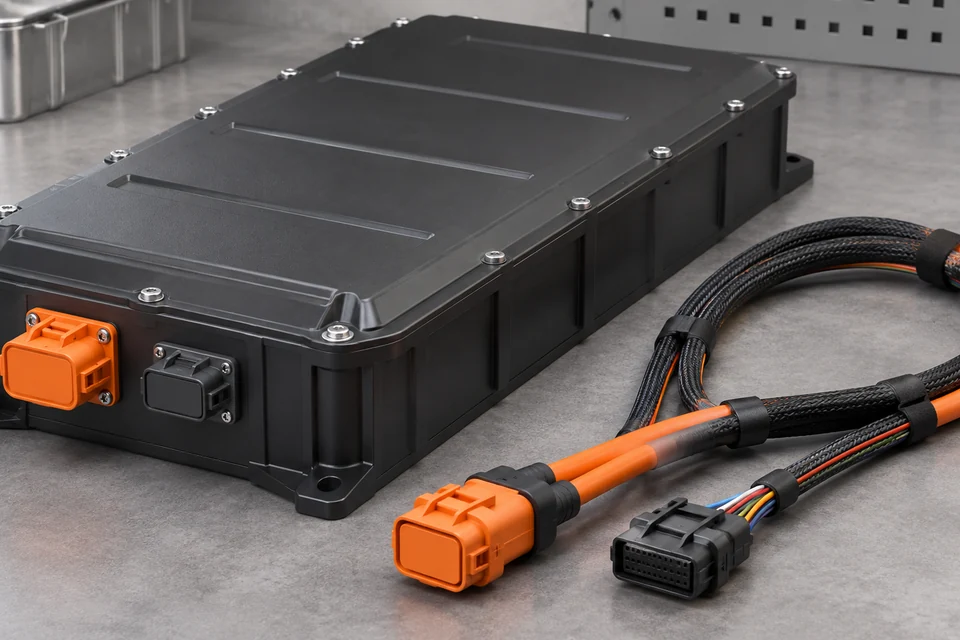
Xinshao develops custom battery wire harnesses around the interfaces inside your battery pack and between the pack, controller, charger and equipment. Power paths and low-current sensing circuits need different cable, termination and inspection decisions.
Specify the pack voltage, continuous and peak current, routing envelope, mating connectors and environmental conditions. We review these inputs with your drawings or sample before agreeing a build specification. The configurations below are customization directions; final assemblies follow your approved BOM.
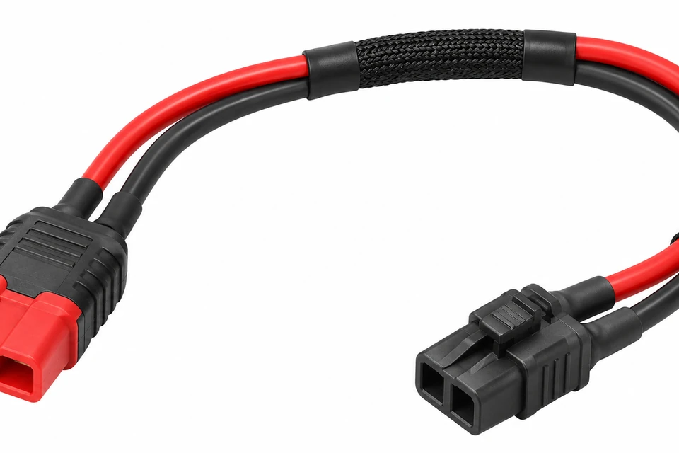
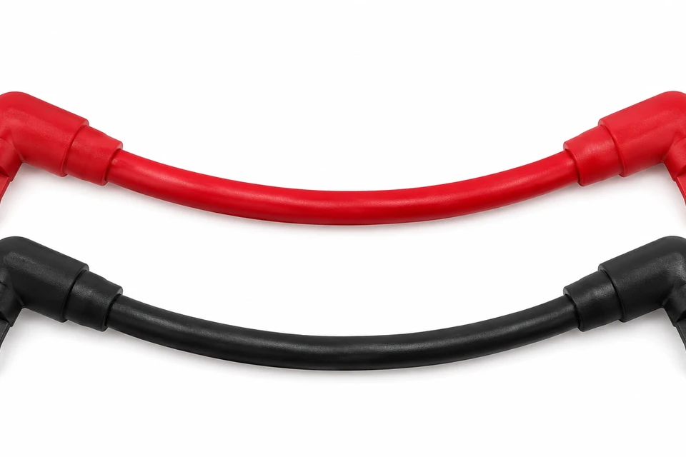
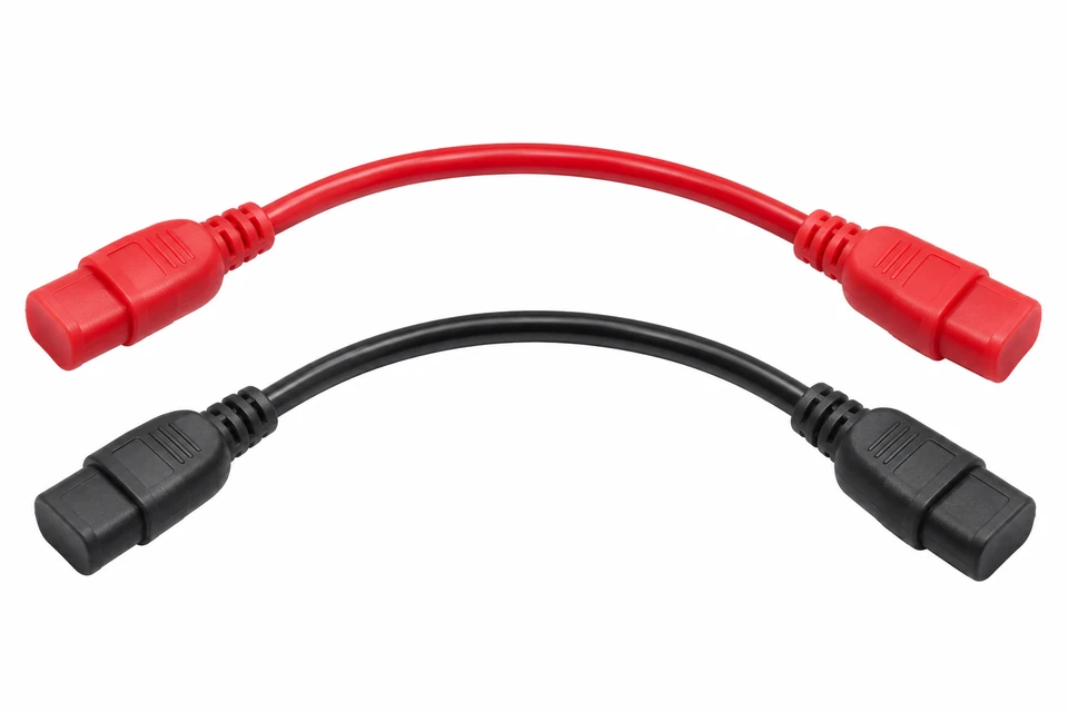
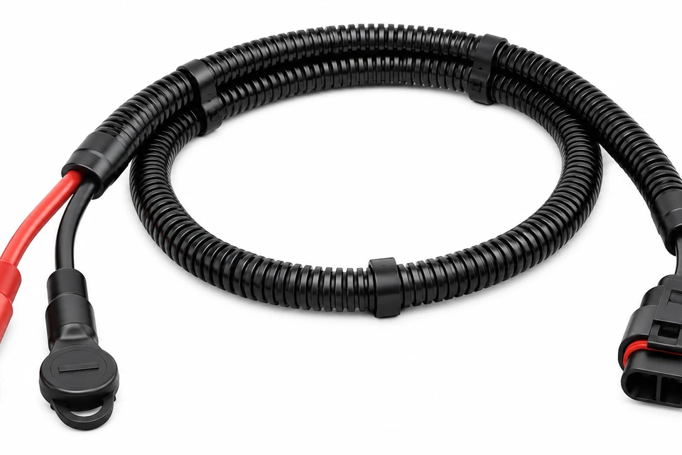
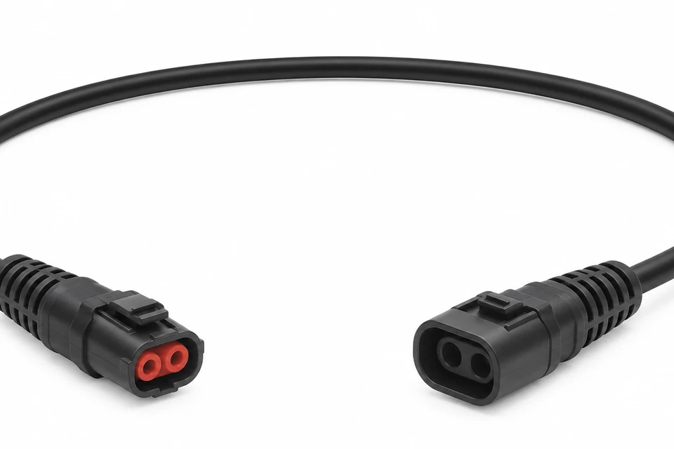
Specify cable gauge, mating power connectors, polarity and routing for your pack-to-equipment connection.
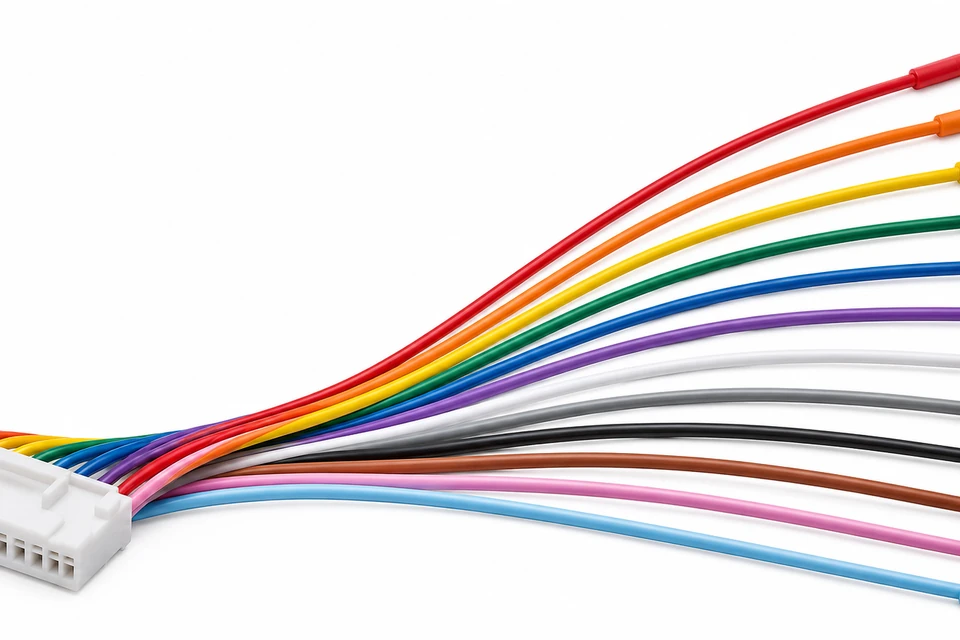
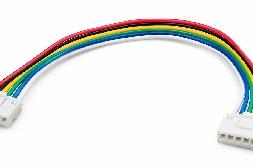
Define cell-tap sequence, connector cavities and branch lengths for the selected battery management system.
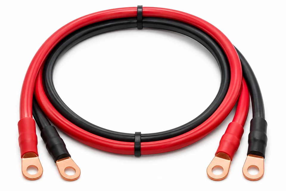
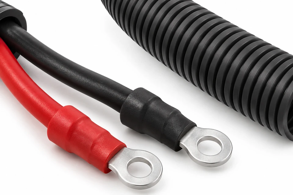
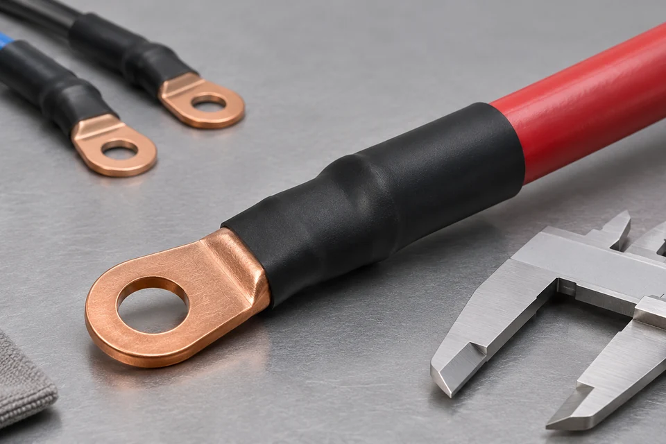
Configure lug hole size, terminal angle, cable length and insulation coverage to match the installation.
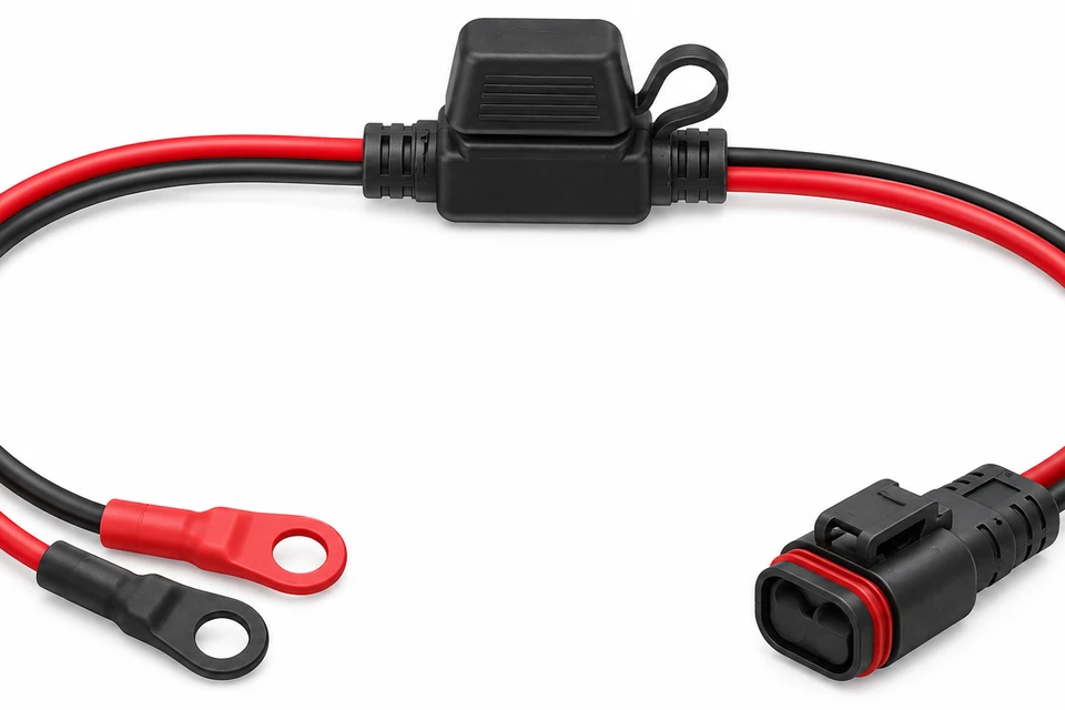
Specify the fuse, holder and service access; protection coordination remains part of the system design.
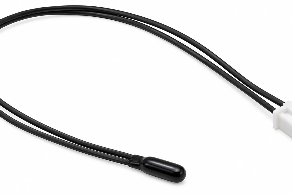
Define sensor characteristic, probe mounting, lead length and interface for temperature monitoring.
Coordinate module spacing, terminal orientation, strain relief and service clearances.
6 Products Found.
01
Specify connectors, wire lengths, branching, protection and labeling for your installation.
02
Discuss your drawings and assembly requirements before starting a new build.
03
Plan prototype and production requirements around the needs of your project.
04
Align drawings, revisions and inspection requirements before manufacture.
A cable gauge alone does not establish a harness current rating. Connector contacts, crimp quality, cable length, bundling, ambient temperature and duty cycle affect the complete assembly. Define peak-current duration and acceptable voltage drop as well as continuous load.
For BMS circuits, confirm cell-tap sequence, polarity, cavity numbering and connector orientation. Agree inspection limits, test points and any sample thermal validation before production. Harness continuity checks do not replace battery-pack safety validation.
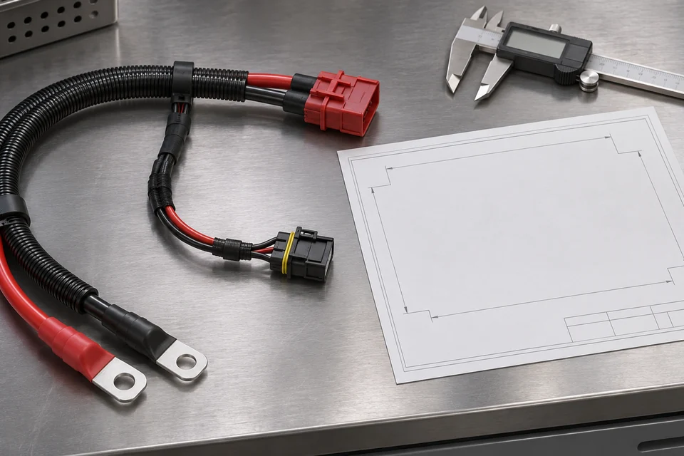
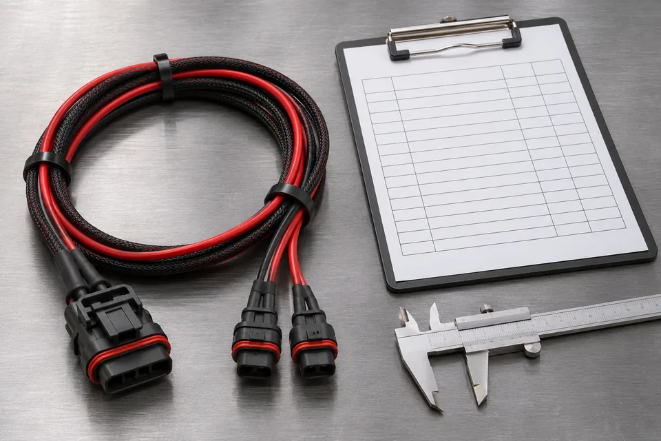
Start with a controlled drawing: connector and terminal part numbers, wire specification, branch lengths, tolerances, pin-to-pin connections, protection and identification. Identify BMS cell-tap order and temperature-sensor characteristics separately from power wiring.
Confirm material availability and tooling during DFM review, then approve a sample against the agreed drawing and inspection plan. Freeze the revision before repeat builds. Connector substitutions require your approval; similar housings do not establish electrical or mechanical equivalence.
Include prototype quantity, production batch size, annual forecast and delivery destination. Sample and production schedules depend on component availability, engineering approval and validation requirements.
Match cable and insulation specifications to pack voltage, temperature, routing and exposure. Material names alone do not establish the rating of a finished assembly.
Define acceptance criteria for the actual build. Agree which checks require recorded results or first-article documentation.
Coordinate pack power outputs, charging interfaces and sensing connections with enclosure clearances and assembly access. Share your system-level requirements for a drawing-based review.
Control connector sourcing, approved alternatives, revision history and inspection documentation. Compare quotations against the same BOM, test coverage and delivery assumptions.
Prepare the right project information for a more useful engineering review and quotation.