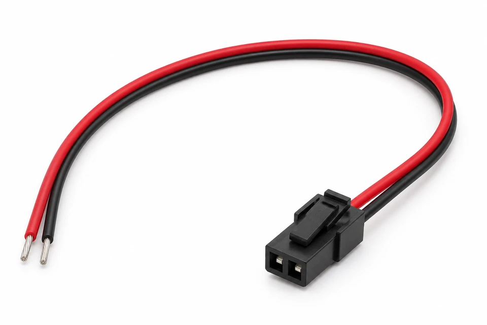
DRAWING-BASED OEM CABLE ASSEMBLIES
JST cable assemblies built around your approved connector parts, pinout and installation layout. Send a drawing, BOM or sample for manufacturing review.
Xinshao supports drawing-based custom JST cable projects for control electronics, sensors and equipment interconnections. Define the interface first: JST names a connector manufacturer, so a series name or pitch alone is not a complete purchasing specification.
Provide full housing and contact part numbers, mating connector details and a numbered pinout. Original JST components can be specified in the BOM; any alternative must be identified separately and approved by you before use. Xinshao is an independent assembly supplier; this page does not imply JST authorization.
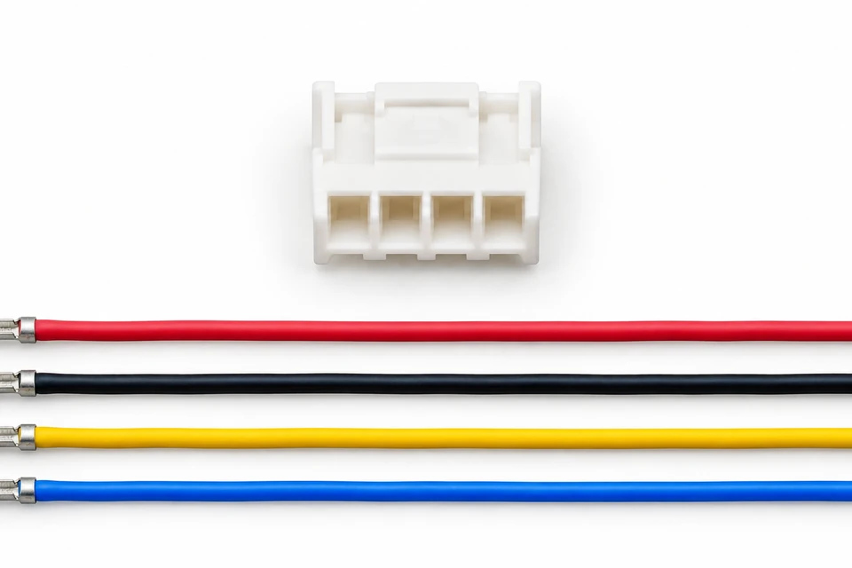
Specify the housing, contact and mating board header as a matched set. Define exit direction, wire size and installed clearance.
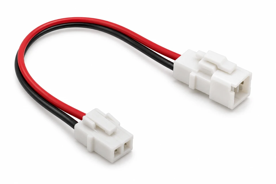
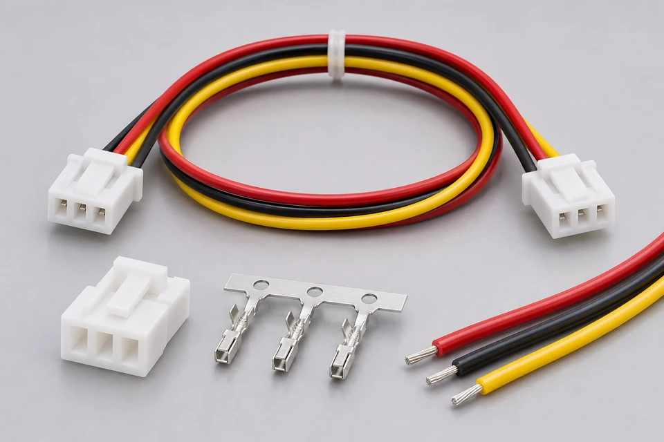
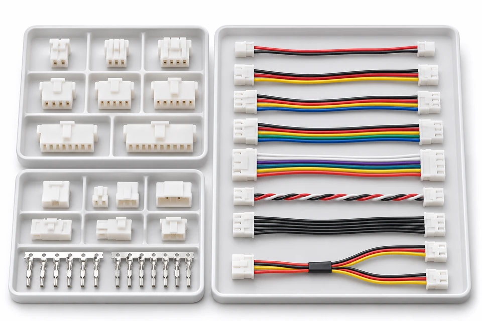
Configure inline connections around the exact mating housings, locking features and circuit assignment required by your equipment.
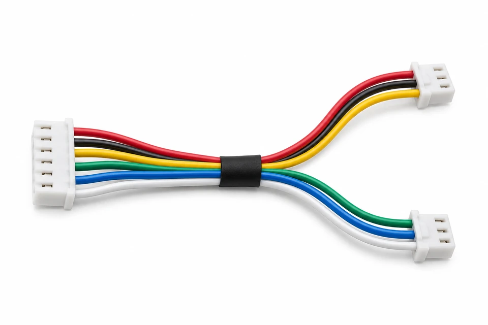
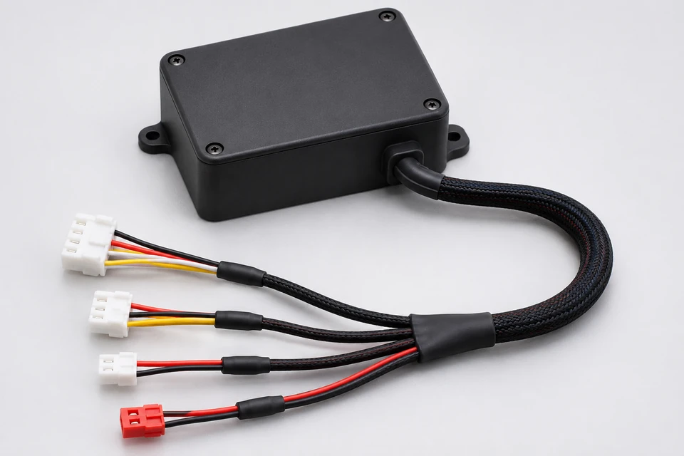
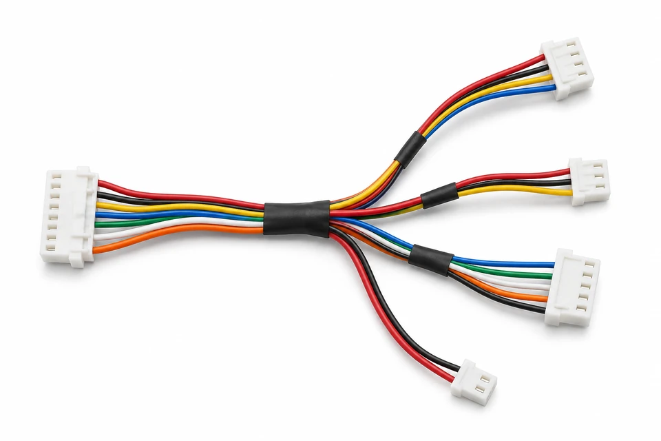
Combine multiple connector ends in a drawing-controlled assembly with branch lengths, breakout positions and identification defined.
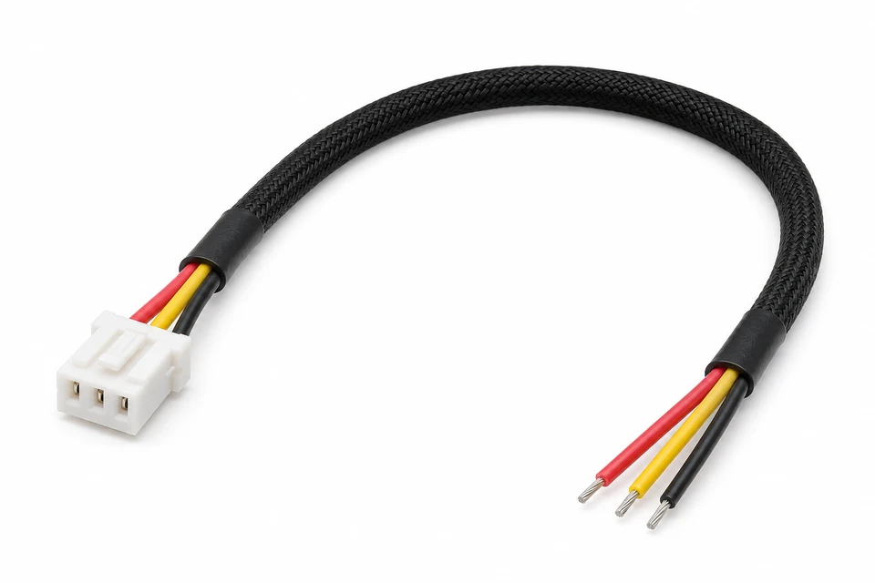
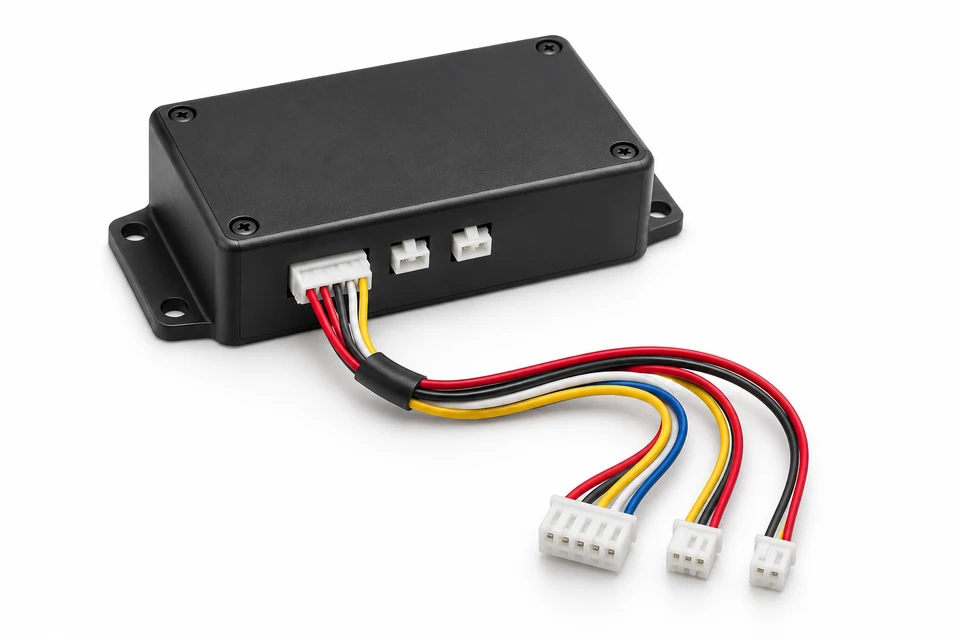
Plan low-level control and sensor connections around pin mapping, routing, noise exposure and strain relief requirements.
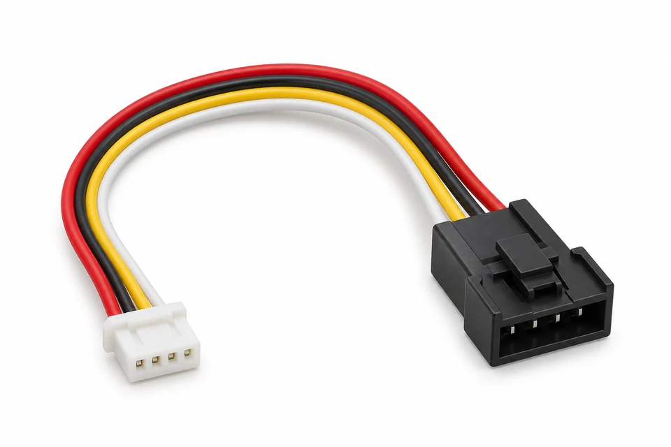
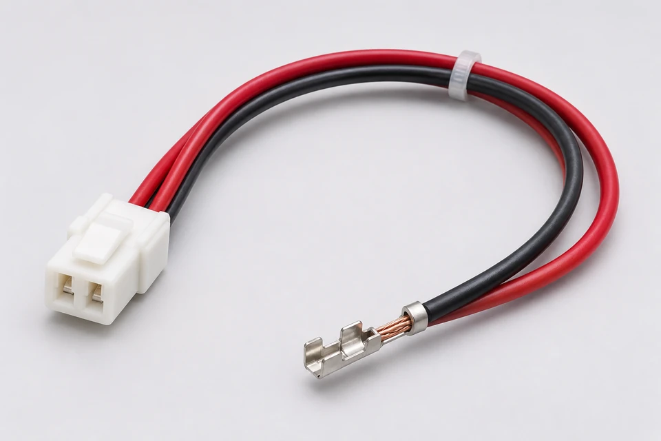
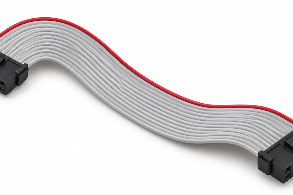
Connect a specified JST interface to another approved connector family. Confirm both mating ends and every circuit before sampling.
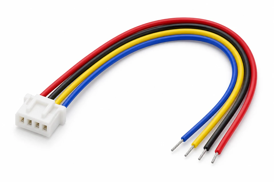
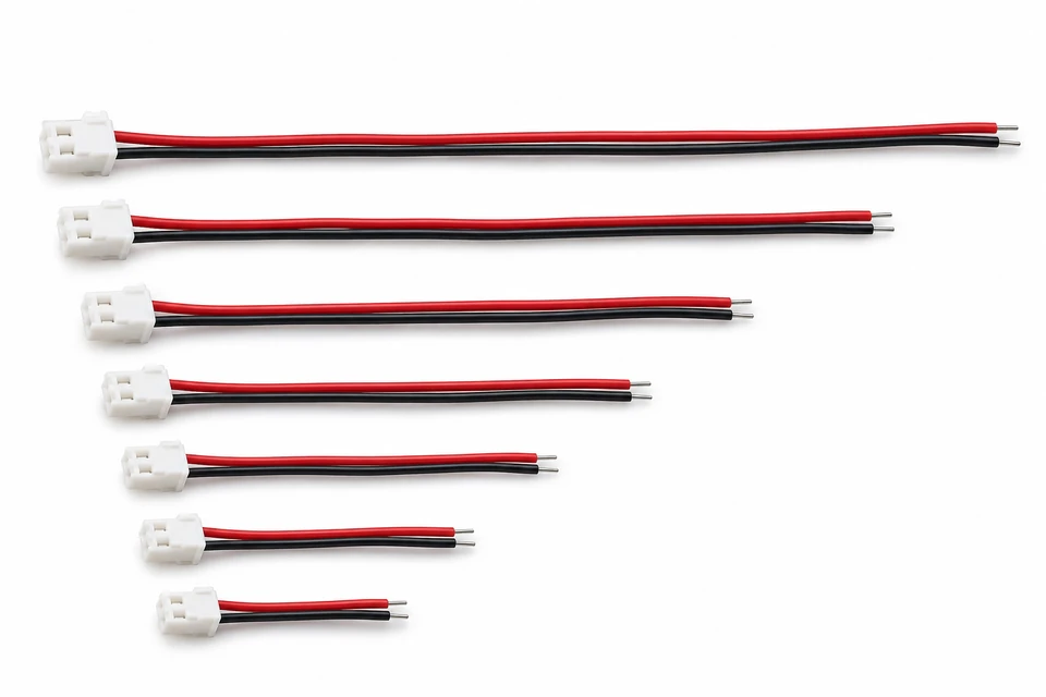
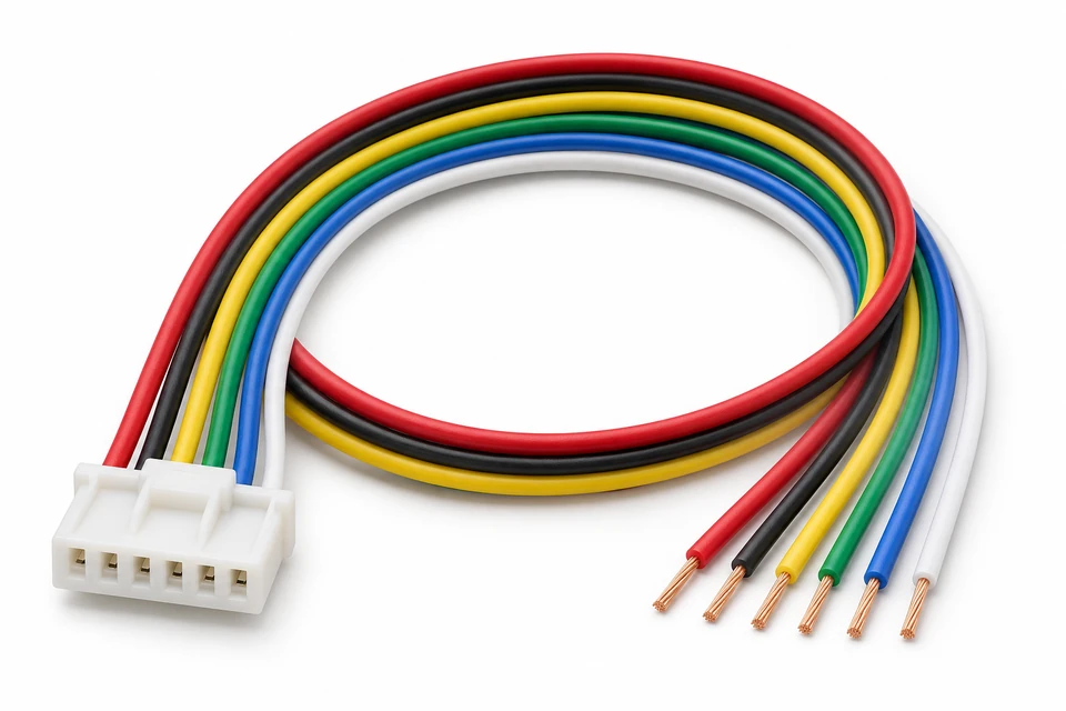
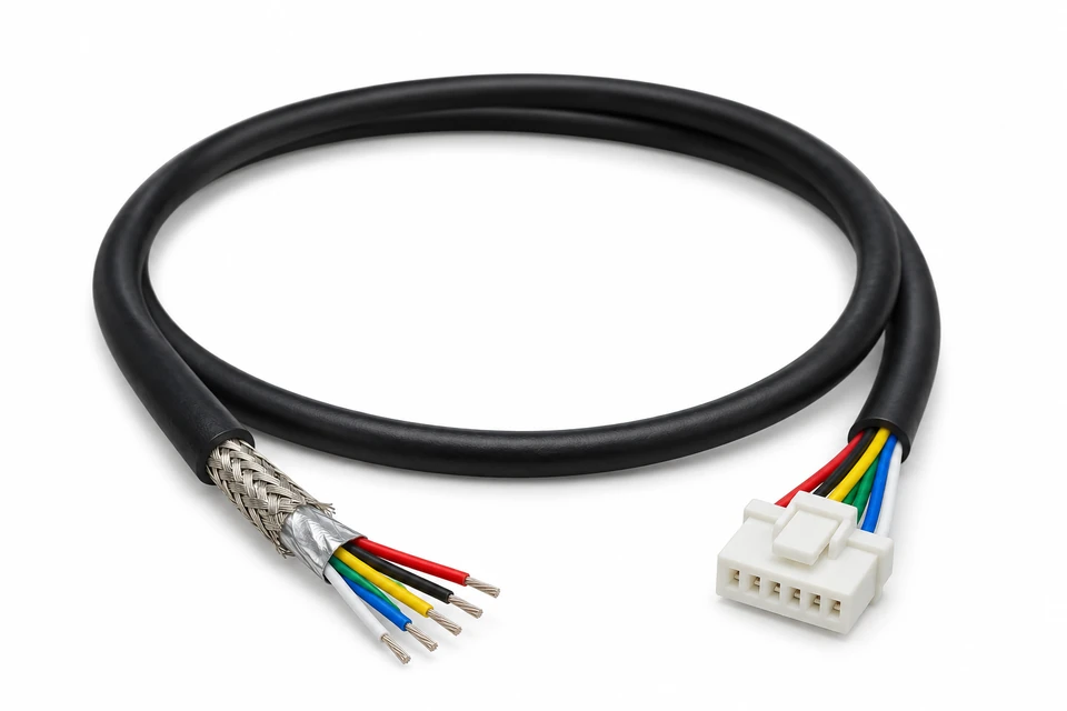
Specify cut length, finished assembly tolerance, wire color and the termination at the free end for repeatable installation.
6 Configuration Directions — Built to Your Approved Specification
01
Specify connectors, wire lengths, branching, protection and labeling for your installation.
02
Discuss your drawings and assembly requirements before starting a new build.
03
Plan prototype and production requirements around the needs of your project.
04
Align drawings, revisions and inspection requirements before manufacture.
A housing that appears similar may use a different contact, latch or mating header. Review the complete part stack, terminal wire range and insulation diameter against the component documentation.
Ask for an agreed BOM, revision-controlled drawing and sample approval criteria. Confirm component provenance requirements, approved substitutions, inspection records and how changes will be authorized before production.
Provide pin numbers with the viewing direction clearly identified: mating face and wire-entry views can reverse the apparent circuit order. Wire colors support identification but do not replace a numbered circuit map.
Dimension connector-to-connector lengths, branches and breakout locations from clear datums. Review bend space and strain relief at the housing; choose sleeving, twisting or shielding only where the application requires it.
For a new project, align requirements and material availability, build samples, approve fit and electrical results, then release the controlled revision for production. Lead time depends on parts availability, quantity and validation scope.
Match conductor size and insulation outside diameter to the exact terminal specification. Determine electrical and environmental requirements from your application, rather than assigning one rating to all JST assemblies.
Agree visual and dimensional inspection, contact retention and circuit checks for your design. Crimp evaluation, pull-force sampling and any additional electrical tests require defined methods and acceptance criteria.
Coordinate the board interface, enclosure space and service access before freezing the assembly. An approved sample should demonstrate fit in your equipment, not just continuity on the bench.
Compare quotations against the same BOM, sourcing requirements, tolerances and test scope. Include sample quantity, production lot sizes, estimated annual usage and delivery destination; tooling and fixtures can affect project cost.
Prepare the right project information for a more useful engineering review and quotation.