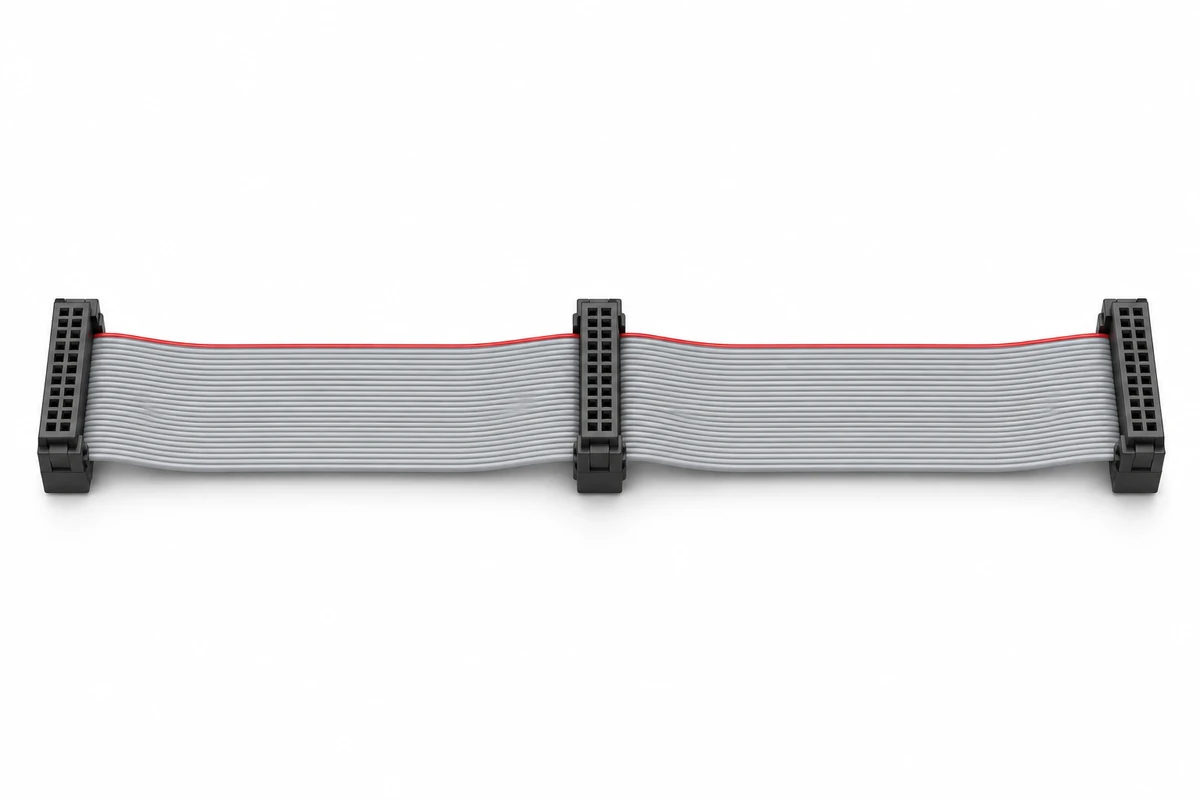
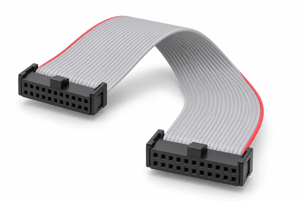
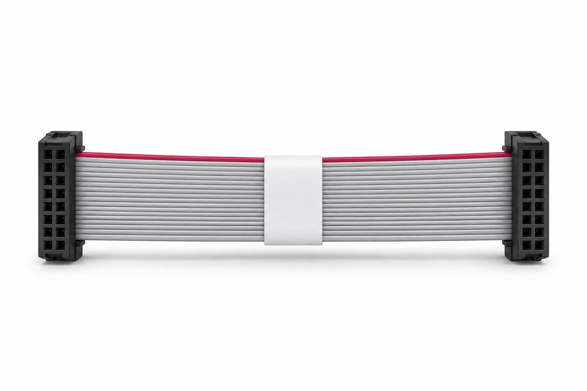
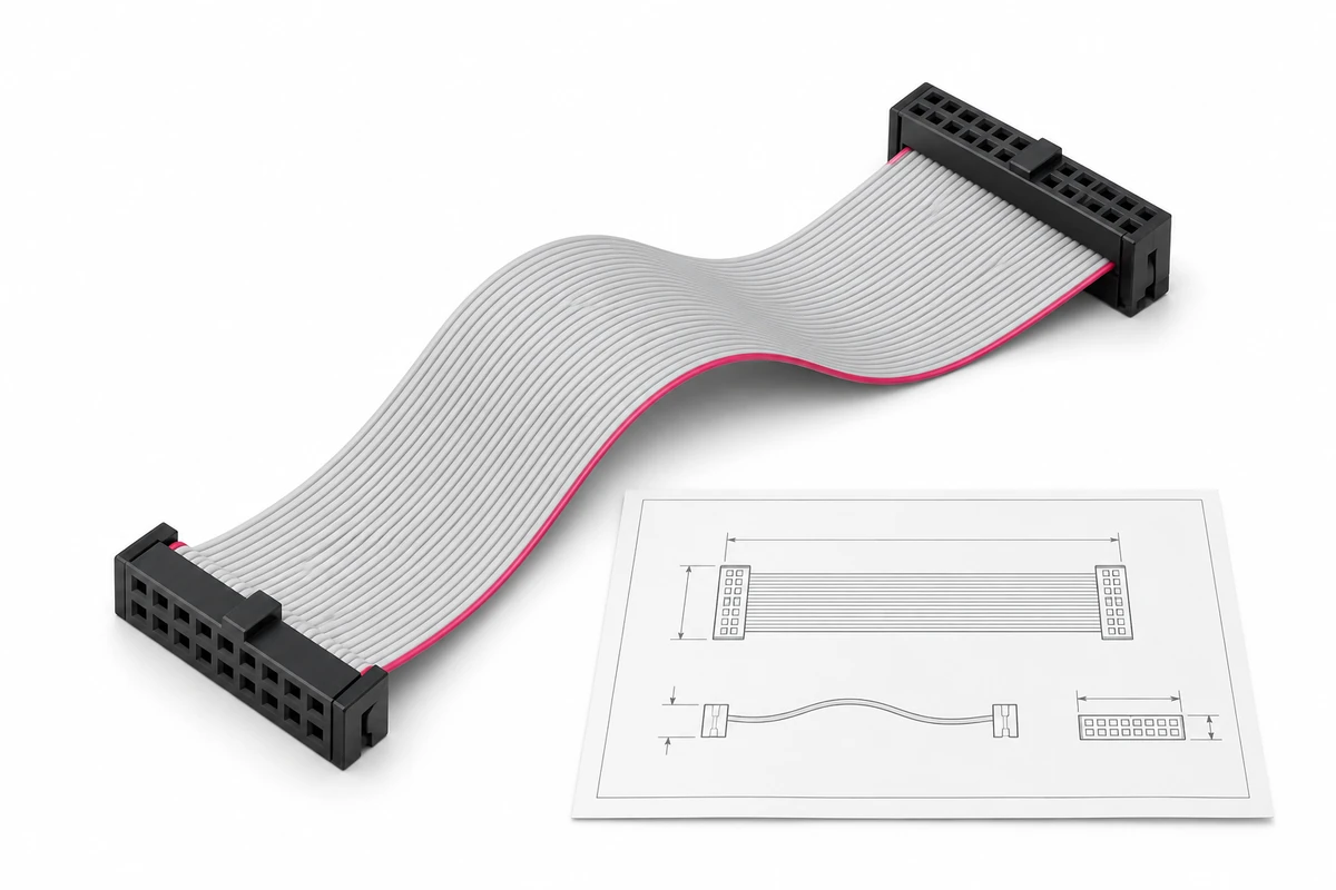
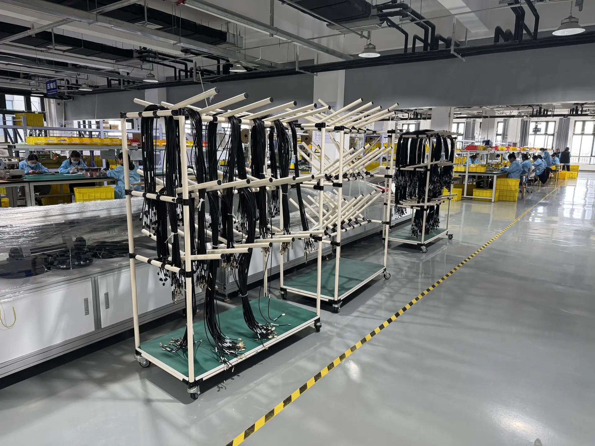
Built around your connections, pinout, and installation space. Share your drawing, connector references, or existing sample to discuss a ribbon cable assembly for your OEM equipment.
Send your drawing, BOM and project requirements for review.
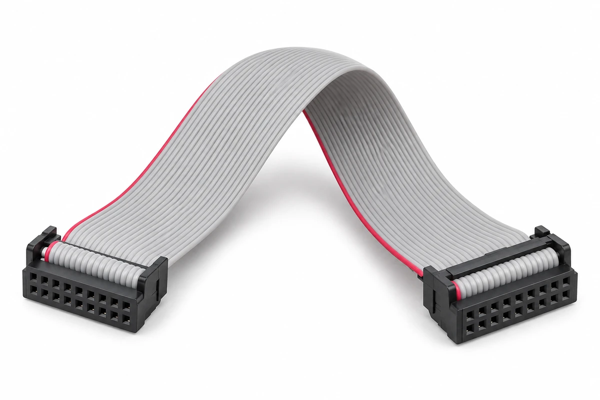
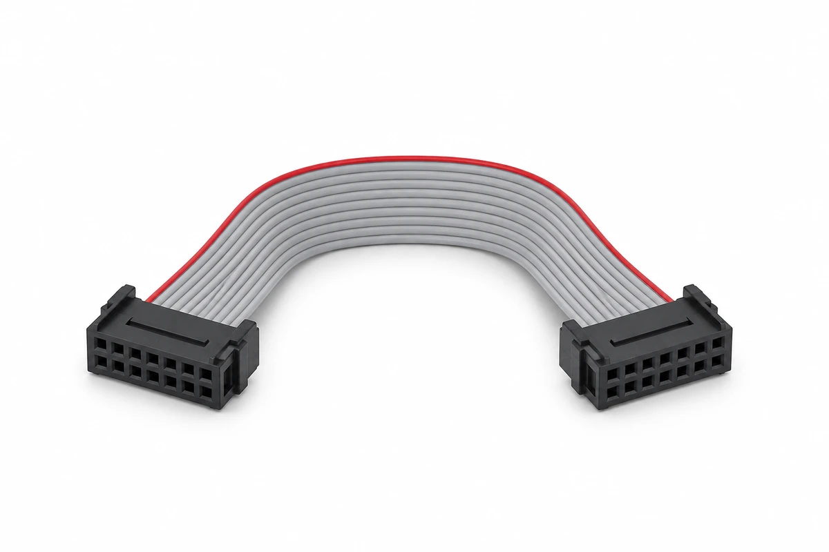
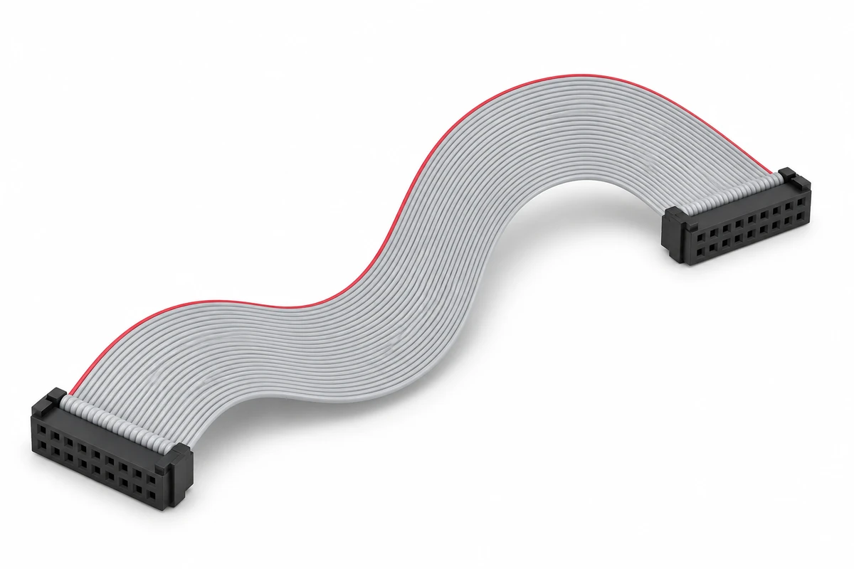
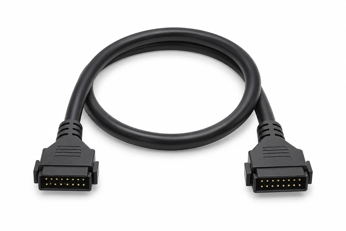
A ribbon cable assembly needs to do more than connect two headers. It must reach the mating interfaces, follow the available routing space, and carry each connection to the correct position. Xinshao supports drawing-, sample-, and BOM-based cable assembly projects for OEM teams.
Start with the mating interfaces and required connection map, then define the cable construction and assembly details. This page focuses on flat multi-conductor ribbon cable assemblies with connectors; FFC and FPC interfaces require separate identification and review.
Review mating headers, compatible ribbon cable, connector orientation, and pin assignments.
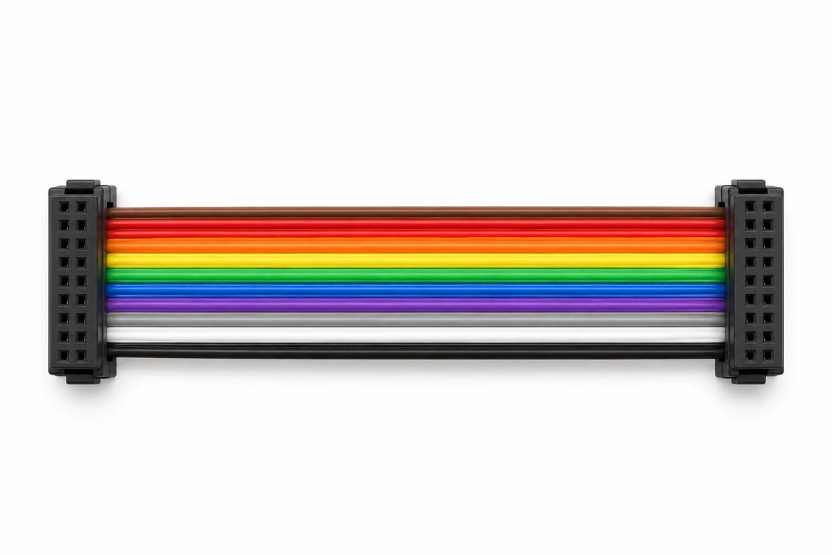
Define conductor identification and connection mapping for equipment assembly and service.
Specify length reference points and tolerances around the installed cable route.
Review folds, clearance, cable exit direction, and installation access in your equipment.
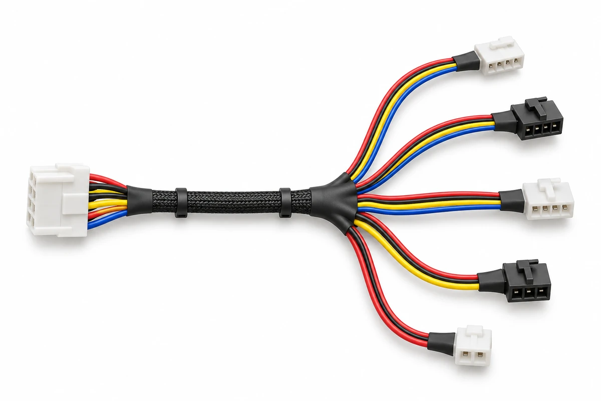
Define each connector location and circuit assignment; configuration is subject to design review.
Document mating-face views, polarization, and pin-1 references at both ends.
Specify assembly identification, drawing revision, and any project labeling requirements.
Bring your drawing, BOM, and approved connection map together for project review.
8 Products Found.
Coordinate equipment connections, branches, and identification around your drawing.
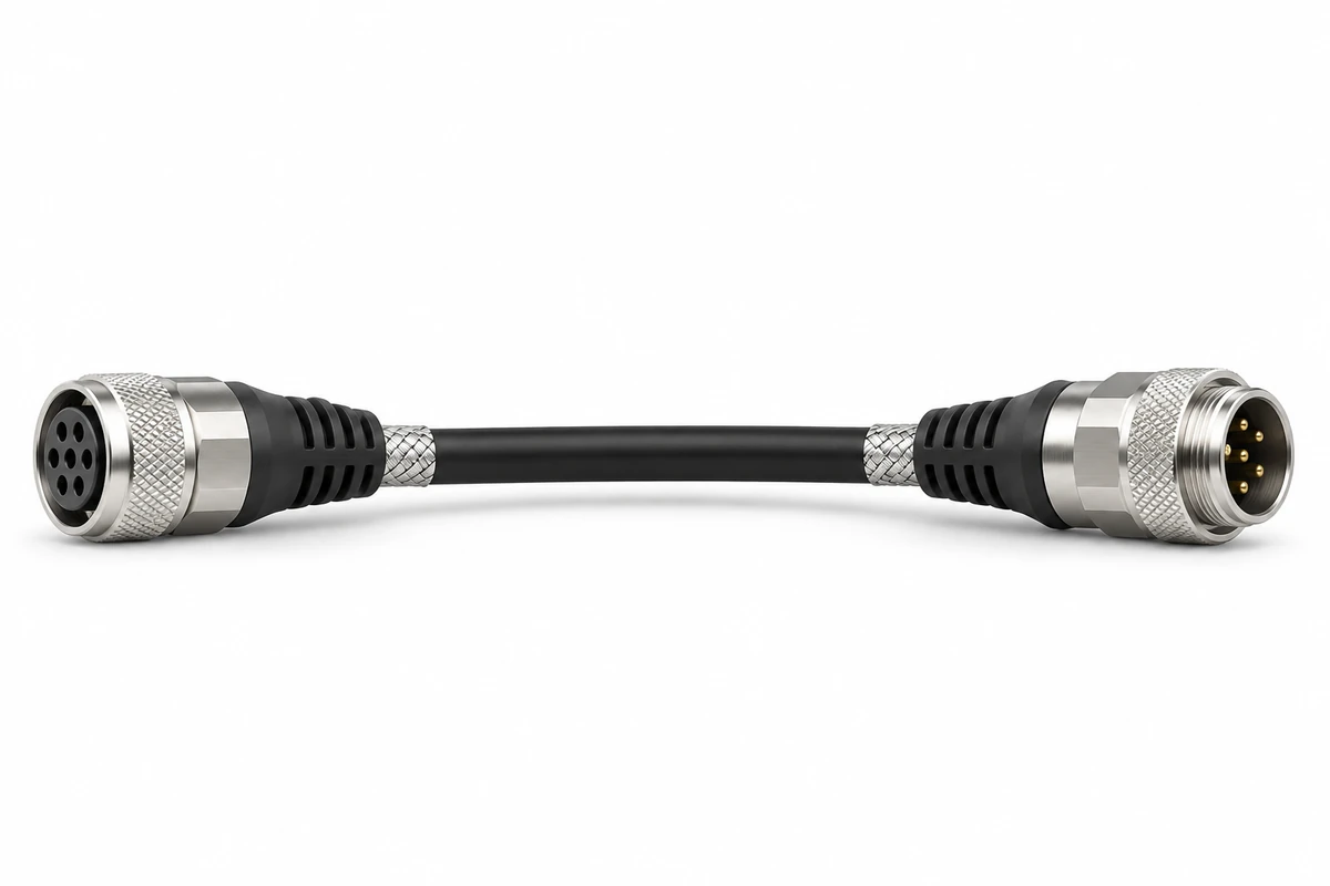
Discuss cable construction and terminations for related equipment connections.
Review shielding and grounding needs where the application requires them.
Provide complete connector part numbers and matching header details.
Review conductor spacing, gauge, insulation, and connector termination requirements together.
Use an explicit pin-to-pin table, including unused positions and intentional cross-connections.
Identify the drawing view, polarization, pin 1, and cable exit direction at both ends.
Define measurement reference points, tolerances, routing space, and service access.
Identify temperature, vibration, abrasion, and any occasional or repeated movement.
State circuit loads and any interface-specific signal, grounding, or validation requirements.
Keep the approved drawing, BOM, labels, and acceptance criteria aligned for repeat orders.
Two ribbon assemblies can look similar while having different electrical connections. Cable conductor spacing and connector contact pitch are separate dimensions: select a compatible cable and connector using their manufacturer specifications. Show pin 1, mating-face views, keying, and cable exit directions, then include a connection table. Do not rely on appearance or the term straight-through alone.
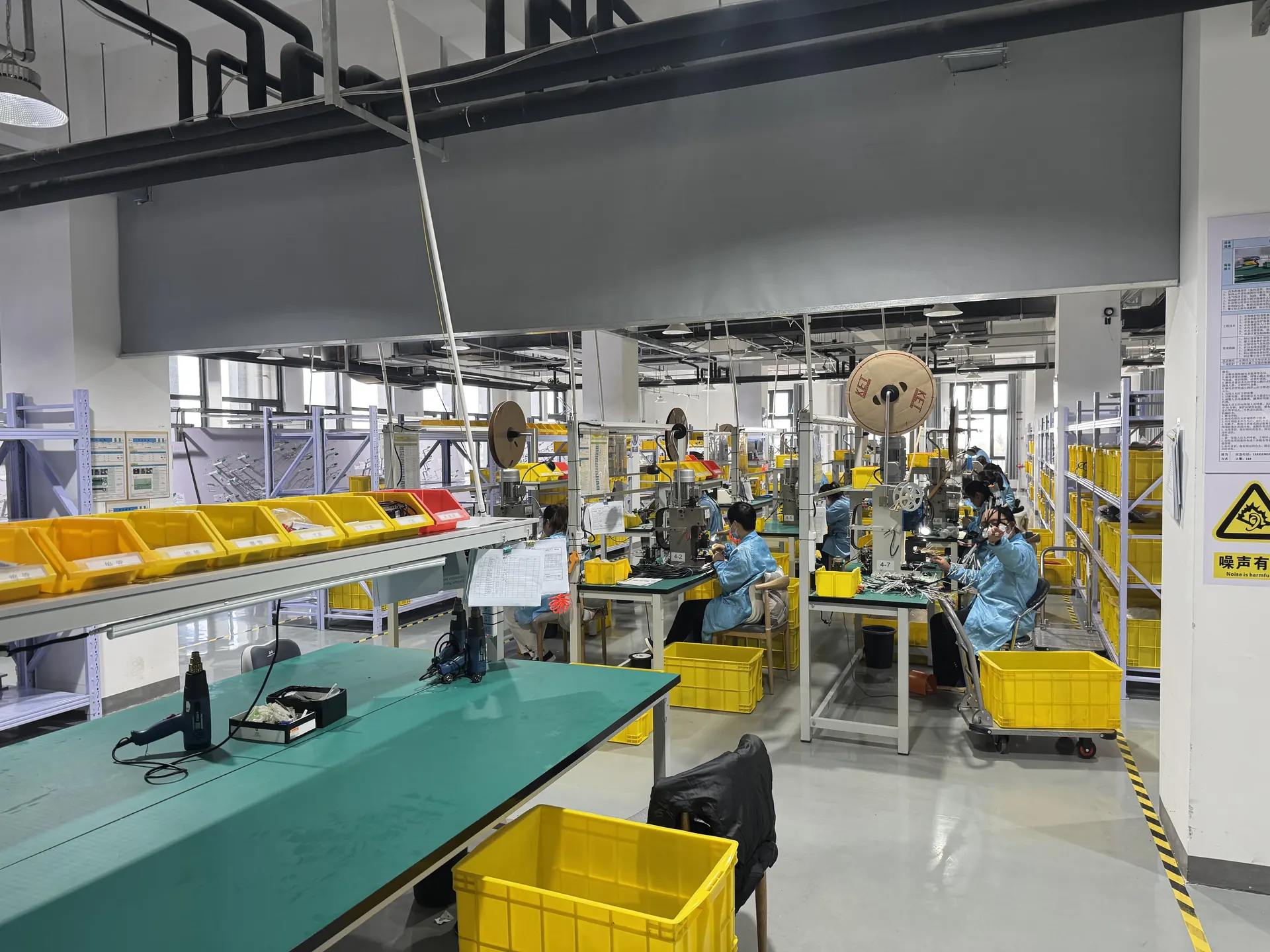
The production specification should identify what is checked, how acceptance is determined, and which records are included. Depending on the design, agree on component identification, dimensions, connector orientation, workmanship, continuity, unintended connections, labels, and packaging. Additional mechanical, electrical, or environmental validation requires agreed test conditions and acceptance limits. Include first-article and traceability needs in the RFQ.
1. Submit the drawing, BOM, mating interfaces, and installation requirements. 2. Resolve cable compatibility, component availability, dimensions, and acceptance criteria. 3. Evaluate the sample in your equipment for fit and the agreed electrical functions. 4. Approve the drawing, connection map, and BOM revision for production. 5. Review changes before repeat orders so earlier and later configurations remain clearly identified.
Send your drawing or sample details, connector references, pinout, cable length, quantities, and delivery destination. List unresolved questions alongside the information you already have.
Provide a drawing or sample photos, connector and mating part numbers, conductor count, length and tolerances, pinout, operating conditions, sample quantity, production quantity, annual demand, inspection needs, and delivery destination. If information is incomplete, identify the open items for review.
An existing assembly can help establish the configuration. Confirm the pinout, dimensions, mating interfaces, cable construction, and operating requirements as well. Appearance alone does not establish electrical or material equivalence.
List cable conductor spacing and connector contact pitch separately. Provide full part numbers and manufacturer drawings, plus pin-1 references, viewing directions, keying, cable exit directions, and an explicit connection table.
These terms can describe different constructions and mating systems. This page covers flat multi-conductor ribbon assemblies with connectors. For an FFC or FPC requirement, provide the interface reference and cable drawing for separate identification.
Connector selection, cable construction, conductor count, configuration, quantity, inspection, documentation, packaging, tooling, and test fixtures can affect cost. Scheduling also depends on component availability, specification approval, sample evaluation, and project preparation. Commercial terms are confirmed per project.
Review proposed component alternatives before approval. Evaluate the sample in the equipment, record changes, and release the agreed drawing, BOM, pinout, and inspection revision. Reference that revision on repeat orders and identify subsequent changes.
Send your drawing, BOM and project requirements for review.